Cleaning head for surface cleaning device

A technology of surface cleaning device and cleaning head, which is applied to cleaning equipment, applications, household appliances, etc. It can solve the problems of reducing the efficiency of floor brush inhaling dirty liquid, secondary pollution of the surface to be cleaned, and occupying space, so as to achieve better anti-backflow effect good effect

Active Publication Date: 2019-01-08
SUZHOU CHENGHE CLEANING EQUIP
View PDF7 Cites 2 Cited by
  • Summary
  • Abstract
  • Description
  • Claims
  • Application Information

AI Technical Summary

Problems solved by technology

[0002] In the prior art, surface cleaning devices such as floor washing machines, cleaning machines, and vacuum cleaners usually include a rod body and a cleaning head that can move on the ground. The suction port for suction, the top of the cleaning head is usually provided with an output port, the inside of the cleaning head is usually provided with a fluid channel connecting the suction port and the output port, the output port is usually connected to a dirty liquid tank, and the dirty liquid tank is usually set On the head or the rod body, the cleaning head or the rod body is usually equipped with a vacuum generating part, which can generate vacuum suction / negative pressure suction in the fluid channel, so that the dirty liquid is transported from the suction port to the output port, due to the fluid When the negative pressure suction in the channel is lost, the dirty liquid that has not entered the dirty liquid tank will enter the fluid channel again from the output port and flow back toward the direction of the suction port. In this way, when the dirty liquid returns to the ground to be cleaned, It will cause secondary pollution to the clean ground
[0003] The Chinese invention patent with the publication number CN206151377U discloses a floor brush and its cleaning machine in its description. When the floor brush is cleaned on the surface to be cleaned, the sewage is easy to flow back from the air flow channel to the surface to be cleaned, causing the cleaning surface to be cleaned. Facing the technical problem of secondary pollution, the following technical scheme is proposed; it uses an anti-backflow assembly 26 set in the air flow channel 20, and the anti-backflow assembly 26 includes a sealing connector 27 and a baffle 28, and the baffle 28 is arranged on the sealing connector 27 The side along the sewage inflow direction prevents the sewage from flowing back to the surface to be cleaned, avoiding secondary pollution of the surface to be cleaned, but the anti-backflow component 26 is always located in the airflow channel 20, occupying the space in the airflow channel 20, so that the dirty liquid must pass through The stopper 28 can enter the first pipe 24, so that part of the dirty liquid will be blocked outside the first pipe 24 by the stopper 28, which reduces the efficiency of the ground brush to suck the dirty liquid

Method used


Image

  • Cleaning head for surface cleaning device
  • Cleaning head for surface cleaning device
  • Cleaning head for surface cleaning device

Examples


no. 1 example

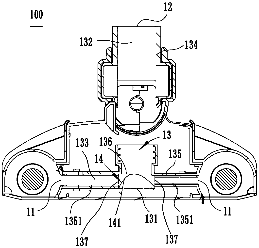
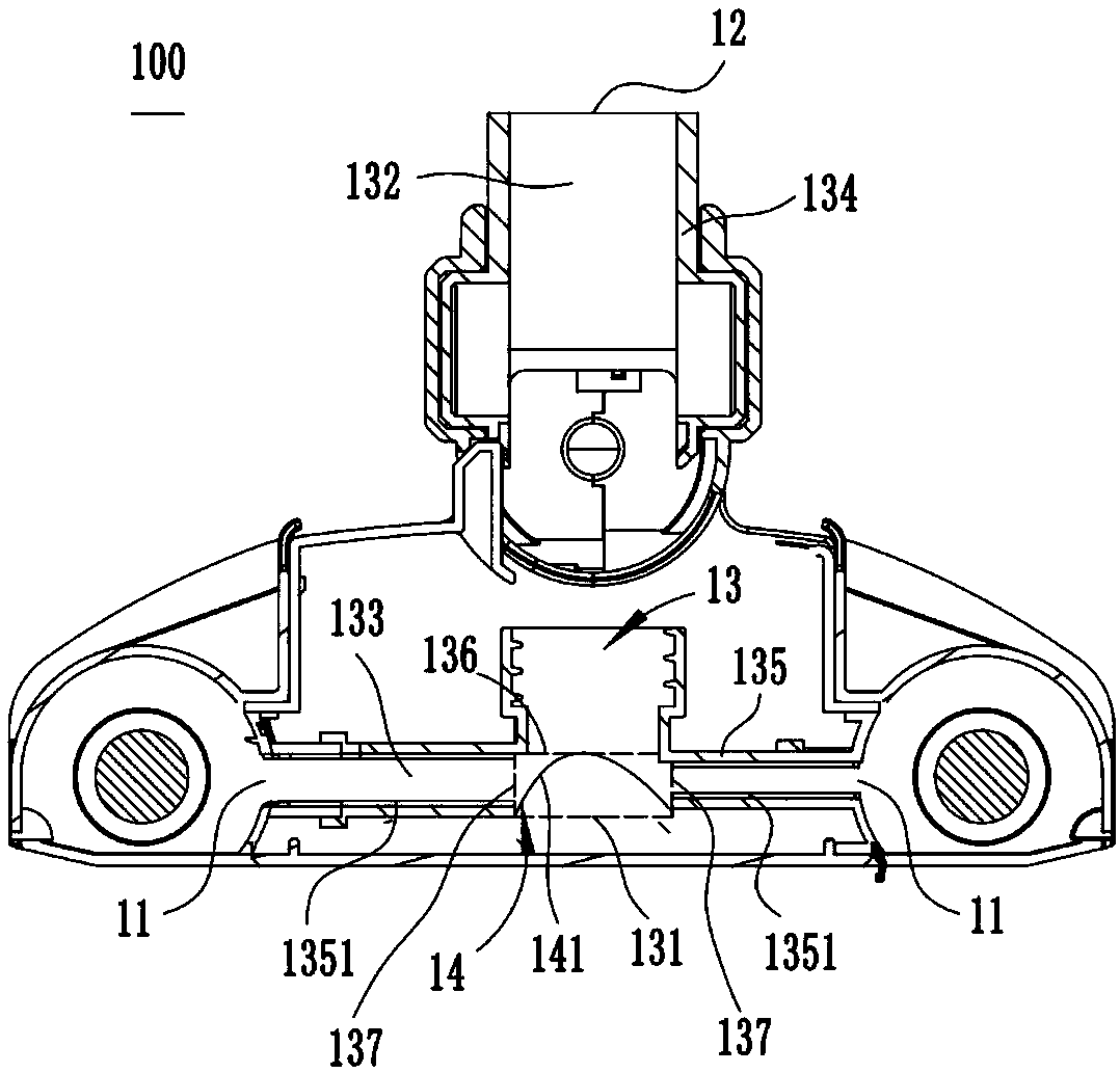
[0030] The first embodiment: the relationship between the upper and lower positions described in this embodiment and the attached figure 1 Corresponds to the up and down positional relationship of the cleaning head shown in ; figure 1 Corresponds to the left direction of the cleaning head shown in figure 1 Corresponds to the right-hand orientation of the cleaning head shown in ; figure 1 Corresponds to the up and down direction of the cleaning head shown in figure 1 Corresponds to the orientation of the horizontal plane in which the cleaning head is shown in .

[0031] According to attached figure 1 As shown, the cleaning head 100 includes a cleaning head body, the bottom front side and the bottom rear side of the cleaning head body are respectively provided with a suction port 11, the top of the cleaning head body is provided with an output port 12, and the inside of the cleaning head body is provided with a fluid channel 13 and The dirty liquid returns to the collecting ...

no. 2 example

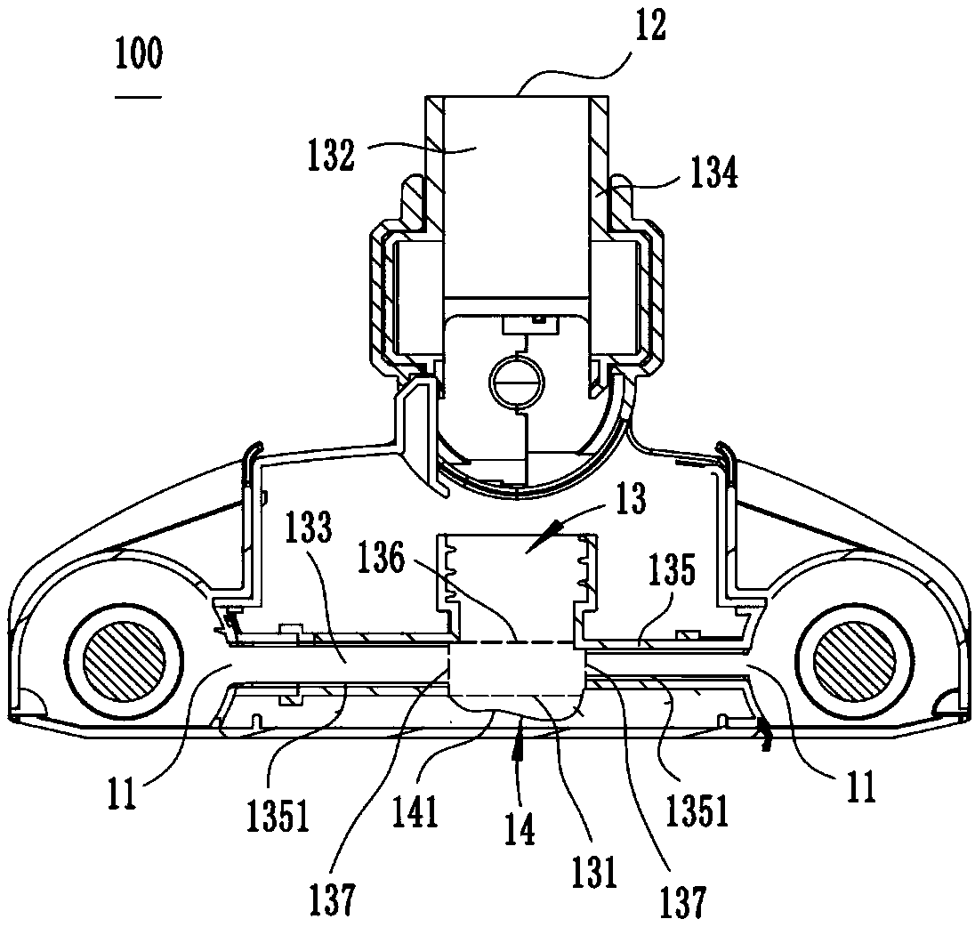
[0043] The second embodiment: the relationship between the upper and lower positions described in this embodiment and the attached Figure 4 Corresponds to the upper and lower positional relationship of the fluid channels shown in .

[0044] According to attached Figure 4 And attached Figure 5 As shown, the fluid channel 23 is provided with a return port 231 with its mouth facing downward, and the return port 231 is located at the lower side of the output port 22 . The fluid channel 23 includes an upstream sub-channel 232 located upstream of the return port 231 and a downstream sub-channel 233 located downstream of the return port 231. The upstream sub-channel 232 includes an end opening 236 near the return port 231, and the end opening 236 is up and down with the return port 231. relatively accurate. Specifically, the upstream channel 232 includes a vertical pipe section 234 , and the end opening 236 is located at the lowermost end of the vertical pipe section 234 . The...


PUM


Abstract

A cleaning head for a surface cleaning device belongs to the technical field of clean equipment, the invention solves the technical problem that the dirty liquid in the fluid channel is easy to returnand causes the secondary pollution of the surface to be cleaned in the prior art, the cleaning head of the present invention comprises a cleaning head body movable on the ground, the cleaning head body includes at least one suction port capable of sucking up dirt liquid on the ground by means of a vacuum suction force, an output port above the suction port, The invention relates to a fluid passage which is fluidly connected with a suction port and an output port and a sewage liquid return collecting device, wherein the flexible liquid storage bag is arranged as a sewage liquid return collecting device, and the flexible liquid storage bag is always in fluid communication with the fluid passage, so that the sewage liquid returned from the output port can always be retained in the fluid passage and collected by the flexible liquid storage bag. As that flexible liquid storage bag can be deform under the vacuum suction force, the dirty liquid store in the flexible liquid storage bag can bepumped away by the fluid channel again under the vacuum suction force, and the backflow prevention effect is better.

Description

technical field [0001] The invention relates to the technical field of cleaning equipment, in particular to a cleaning head for a surface cleaning device. Background technique [0002] In the prior art, surface cleaning devices such as floor washing machines, cleaning machines, and vacuum cleaners usually include a rod body and a cleaning head that can move on the ground. The suction port for suction, the top of the cleaning head is usually provided with an output port, the inside of the cleaning head is usually provided with a fluid channel connecting the suction port and the output port, the output port is usually connected to a dirty liquid tank, and the dirty liquid tank is usually set On the head or the rod body, the cleaning head or the rod body is usually equipped with a vacuum generating part, which can generate vacuum suction / negative pressure suction in the fluid channel, so that the dirty liquid is transported from the suction port to the output port, due to the f...

Claims


Application Information

Patent Timeline
IPC IPC(8): A47L7/00
CPCA47L7/0009A47L7/0023
Inventor 卞庄
Owner SUZHOU CHENGHE CLEANING EQUIP
Why Eureka
Try Eureka