Backflow-preventing hemostatic propeller

An anti-reflux and hemostatic agent technology, applied in the field of medical devices, can solve problems such as limited hemostatic operation effect, difficult to achieve hemostasis, and ineffective hemostasis, and achieve the effect of ensuring and improving the anti-reflux effect

Active Publication Date: 2021-02-26
THE FIRST MEDICAL CENT CHINESE PLA GENERAL HOSPITAL
View PDF15 Cites 0 Cited by
  • Summary
  • Abstract
  • Description
  • Claims
  • Application Information

AI Technical Summary

Problems solved by technology

At present, the commonly used first aid hemostasis methods are commonly used and simple hemostasis methods, the main hemostasis drugs and bandages, but no matter which of the two is the hemostasis operation on the patient's body surface, and the bleeding point of the penetrating injury is located in the cavity. Internal, so the effect of hemostasis on the body surface is relatively limited, and it is often ineffective for common deep cavity wounds. Hemostasis cannot be achieved by ordinary bandaging, and it is difficult to achieve hemostasis by ligation and compression
[0003] In the prior art, there have also been technical means to go deep into the cavity wound to stop bleeding, but the disadvantage is that the front end of the injection vessel is relatively thick. For penetrating wounds, such as gunshot wounds and stab wounds, because of the small wound area, there are It is not easy to insert into the wound, the efficiency is low, and it is easy to aggravate the shortcomings of the patient's pain
In addition, a hemostatic agent propeller can be used for hemostasis, but the problem in the prior art is that the propeller is not easy to propel due to its slow speed during the propulsion process. , leading to blood backflow, causing the hemostatic agent to agglomerate and block at the outlet

Method used


Image

  • Backflow-preventing hemostatic propeller
  • Backflow-preventing hemostatic propeller
  • Backflow-preventing hemostatic propeller

Examples


Embodiment 1

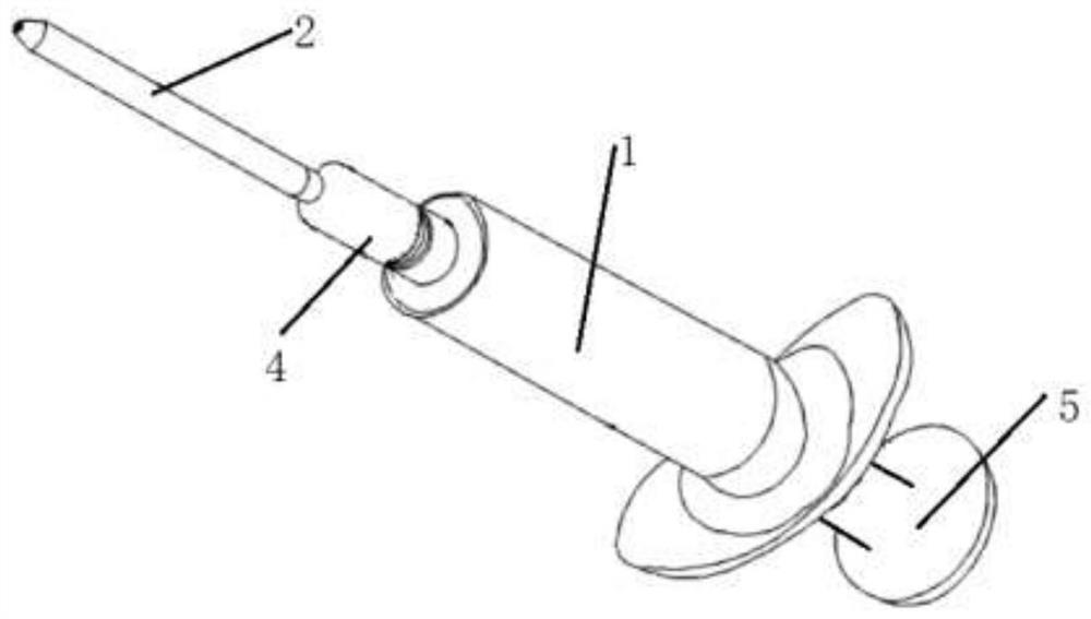
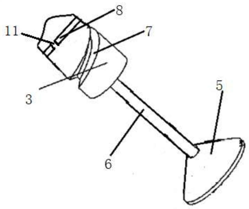
[0030] see Figure 1-4 , an anti-reflux hemostatic agent propeller, comprising a cylinder body 1, a propulsion tube 2, a piston 3, a tube connector 4, an enlarged portion 5 and a piston rod 6, a piston 3 is arranged in the cylinder body 1, and the front end of the cylinder body 1 It has a liquid outlet that tapers into a thin cylinder in a conical shape; the propulsion tube 2 is connected to the liquid outlet through a tube connector 4, the piston 3 is arranged at one end of the piston rod 6, and the other end of the piston rod 6 is provided with an enlarged part 5 , allowing the piston rod 6 to be moved manually;

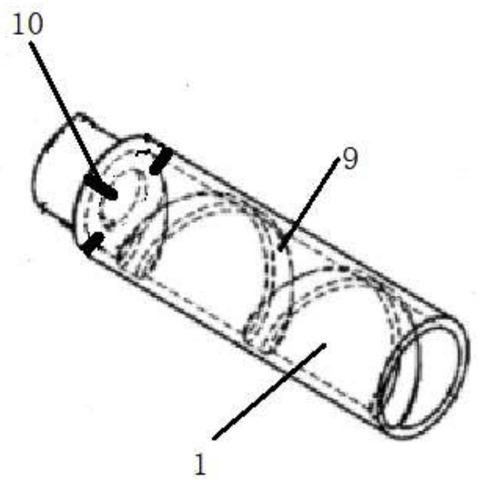
[0031] The circumference of the piston 3 is provided with a threaded groove 7 of a continuous spiral track from the front end to the rear end, and a plurality of anti-backflow limiting depressions 8 are evenly spaced on the front end of the threaded groove 7 along the circumference of the piston 3 . A threaded protrusion 9 with a continuous spiral track from the r...

Embodiment 2

[0042] see Figure 1-4 , an anti-reflux hemostatic agent propeller, comprising a cylinder body 1, a propulsion tube 2, a piston 3, a tube connector 4, an enlarged portion 5 and a piston rod 6, a piston 3 is arranged in the cylinder body 1, and the front end of the cylinder body 1 It has a liquid outlet that tapers into a thin cylinder in a conical shape; the propulsion tube 2 is connected to the liquid outlet through a tube connector 4, the piston 3 is arranged at one end of the piston rod 6, and the other end of the piston rod 6 is provided with an enlarged part 5 , allowing the piston rod 6 to be moved manually;

[0043] The circumference of the piston 3 is provided with a threaded groove 7 of a continuous spiral track from the front end to the rear end, and a plurality of sections of anti-backflow limiting depressions 8 are evenly spaced along the circumference of the piston 3 at the front end of the threaded groove 7. A threaded protrusion 9 with a continuous spiral track...

Embodiment 3

[0068] see Figure 1-4, an anti-reflux hemostatic agent propeller, comprising a cylinder body 1, a propulsion tube 2, a piston 3, a tube connector 4, an enlarged portion 5 and a piston rod 6, a piston 3 is arranged in the cylinder body 1, and the front end of the cylinder body 1 It has a liquid outlet that tapers into a thin cylinder in a conical shape; the propulsion tube 2 is connected to the liquid outlet through a tube connector 4, the piston 3 is arranged at one end of the piston rod 6, and the other end of the piston rod 6 is provided with an enlarged part 5 , allowing the piston rod 6 to be moved manually;

[0069] The circumference of the piston 3 is provided with a threaded groove 7 of a continuous spiral track from the front end to the rear end, and a plurality of anti-backflow limiting depressions 8 are evenly spaced on the front end of the threaded groove 7 along the circumference of the piston 3 . A threaded protrusion 9 with a continuous spiral track from the re...


PUM

PropertyMeasurementUnit
impact strengthaaaaaaaaaa
elongation at breakaaaaaaaaaa

Abstract

The invention provides a backflow-preventing hemostatic propeller. The backflow-preventing hemostatic propeller comprises a barrel (1), a propelling pipe (2), a piston (3), a pipe barrel connector (4), an expanding part (5) and a piston rod (6), wherein a threaded groove (7) with a continuous spiral track is formed in the circumference of the piston (3); a backflow-preventing limiting concave part(8) is formed in the front end of the threaded groove (7) along the circumference of the piston (3); a threaded protrusion (9) with a continuous spiral track is arranged on the circumference of the inner wall of the barrel (1); a backflow-preventing limiting clamping block (10) is arranged at the front end of the threaded protrusion (9) along the circumference of the inner wall of the barrel (1);a backflow-preventing one-way blocking structure is arranged at the end, connected with a liquid outlet of the barrel (1), of the pipe barrel connector (4) and comprises a supporting blocking frame (12) and a backflow-preventing one-way blocking piece (13); and the backflow-preventing one-way blocking piece (13) is of an inner-outer-layer structure. The backflow-preventing hemostatic propeller issimple in structure, convenient to operate and easy to propel, and the backflow-preventing effect of the hemostatic propeller is improved.

Description

technical field [0001] The invention relates to the field of medical devices, in particular to an anti-reflux hemostat propeller. Background technique [0002] Penetrating injury is one of the main injury types of trauma. Penetrating injury can cause a hollow wound on the human body, and the hollow wound can cause massive blood loss. At present, the commonly used first aid hemostasis methods are commonly used and simple hemostasis methods, the main hemostasis drugs and bandages, but no matter which of the two is the hemostasis operation on the patient's body surface, and the bleeding point of the penetrating injury is located in the cavity. Internally, the effect of hemostatic operation on the body surface is relatively limited, and it is often ineffective for hemostasis on common deep cavity wounds. Hemostasis cannot be achieved by ordinary bandaging, and it is difficult to achieve hemostasis by ligation and compression. [0003] In the prior art, there have also been tech...

Claims


Application Information

Patent Timeline
Patent Type & Authority Applications(China)
IPC IPC(8): A61M37/00C08L29/04C08L67/04C08L75/04C08L1/28C08K13/02C08K3/16C08K5/053C08K3/22C08K5/07C08L9/06C08L23/06C08L23/22C08K3/26C08K3/36C08K5/14C08L33/16C08F220/22C08F222/14
CPCA61M37/00C08L29/04C08L9/06C08L67/04C08K3/22C08F220/22C08L2205/035C08L2205/025C08K2003/162C08K2003/222C08K2201/011C08K2003/265C08K2003/2241C08L75/04C08L1/286C08K13/02C08K3/16C08K5/053C08K5/07C08L33/16C08L23/06C08L23/22C08K3/26C08K3/36C08K5/14C08F222/102
Inventor 冯聪陈力黄赛杨博滕玥崔翔陈骅王莉荔
Owner THE FIRST MEDICAL CENT CHINESE PLA GENERAL HOSPITAL
Why Eureka
Try Eureka