A rotary power connection device

A technology of power connection and rotation, which is applied to the parts of the connection device, flexible/rotatable wire connectors, connections, etc., which can solve the problem that the ultrasonic signal of the ultrasonic generator cannot be smoothly transmitted to the vibrator head, affecting water quality, and inconvenient to handle and other problems, to achieve the effect of good waterproof function, good sealing effect and simple structure

Pending Publication Date: 2019-01-04
HUNAN LOUDI TAIYANG TECH
View PDF0 Cites 0 Cited by
  • Summary
  • Abstract
  • Description
  • Claims
  • Application Information

AI Technical Summary

Problems solved by technology

[0002] Industries such as iron and steel metallurgy, petrochemical, power generation or papermaking at home and abroad need to use a lot of water. It is a difficult problem to treat the sewage in the transition device / pool in their water treatment system or water circulation system, because the filter / pool Dirt will affect the quality of water and bring a lot of inconvenience to subsequent treatment
Although those skilled in the art have designed / manufactured various types of equipment and devices, such as high-pressure water washing devices, etc., which play their respective roles, there are also tools used for manual cleaning / rinsing, which are primitive and unsafe
In addition, when using the ultrasonic generator and the matching vibrator head to wash / clean the dirt in the filter / pool, when the entire cleaning device rotates 0 to 360°N, the gap between the ultrasonic generator and the vibrator head There will often be problems with the connection of the ultrasonic generator, so that the ultrasonic signal of the ultrasonic generator cannot be smoothly transmitted to the vibrator head
There are no related reports on solving this problem

Method used


Image

  • A rotary power connection device

Examples


Embodiment Construction

[0007] The specific implementation manners of the present invention will be further described in detail below in conjunction with the accompanying drawings.

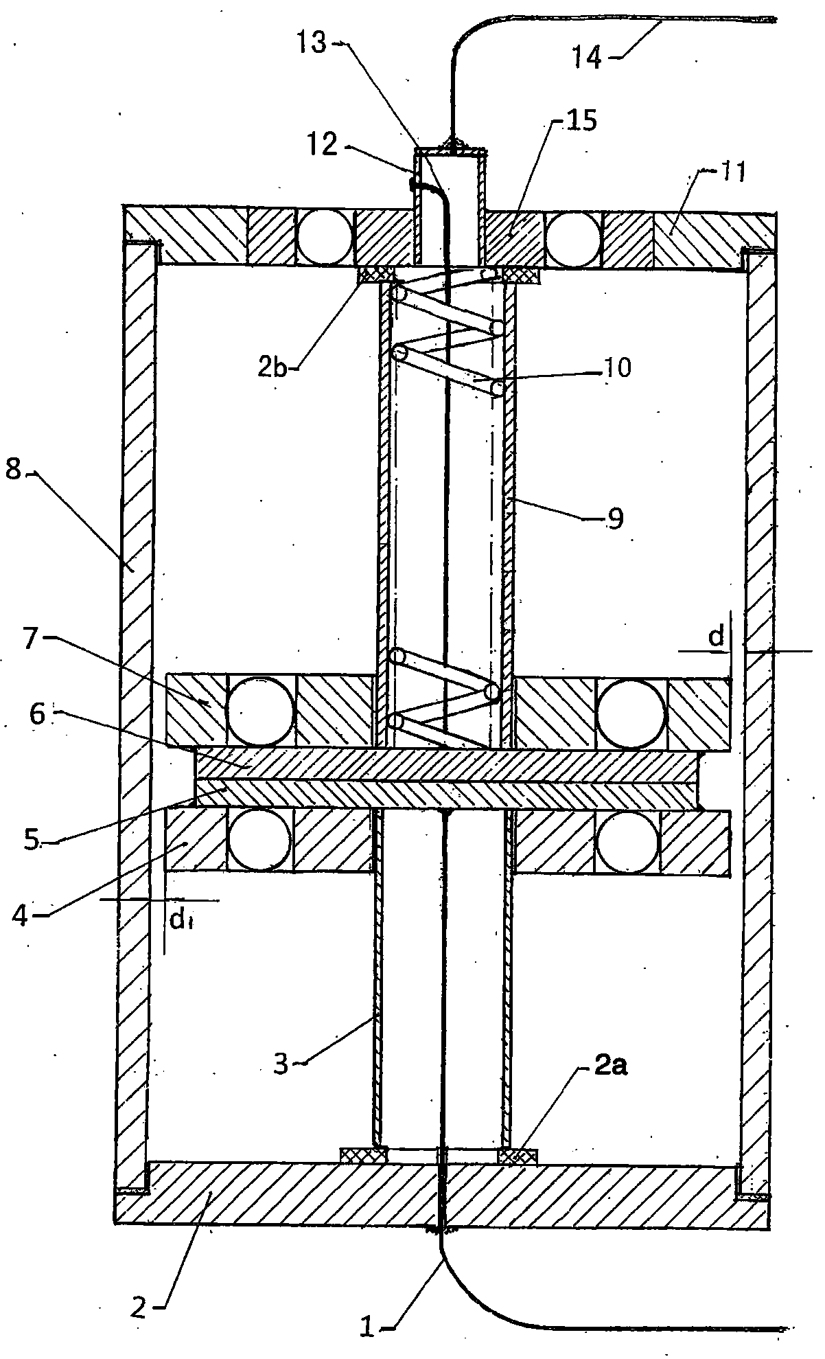
[0008] as attached figure 1 As shown, a rotary power supply connection device (also called a rotary signal source connection device) according to the present invention includes a vibrator head wire 1, a screw-down sealing cover 2, a lower inner sealing ring 2a, a lower cavity Sleeve 3, lower rotating body 4, lower rotating conductive plate 5, upper rotating conductive plate 6, upper rotating body 7, sheath 8, upper cavity casing 9, spring ring 10, upper rotating sealing cover 11, upper inner sealing ring 2b. Terminal post / box 12, ultrasonic source wire 13, ultrasonic current output line 14 and top rotating body 15, wherein the lower rotating body 4, upper rotating body 7 and top rotating body 15 can use rolling bearings of different specifications or the same specification Or rolling bearing structural products, and the...


PUM


Abstract

The invention discloses a rotary power supply connecting device, An upper rotate conductive plate and a lower rotate conductive plate are respectively that same as the upper rotating conductive plate,the surface of the lower rotating body is fixedly connected, An upper part is fit in a central circular hole of that upper and lower rotary body, lower lumen cannula, the lower end of the spring coildisposed in the upper cavity sleeve is in contact with the surface of the upper rotating conductive plate, located above the barrel lumen, The lower rotating body is spaced apart from the protectivebarrel wall, and upper and lower rotating seal caps with sealing rings are screwed on the upper and lower ends of the protective barrel, and a top rotating body is arranged at the center of the upperrotating seal cap, and upper and lower inner seal rings are arranged between the top rotating body and the upper cavity sleeve, and the lower rotating seal cap and the lower cavity sleeve, so as to form a multi-level mechanical seal. The two ends of the vibrator head conductor are connected with the lower rotating conductive plate and the contact of the vibrator head, the two ends of the ultrasonic source conductor are connected with the upper rotating conductive plate and the terminal, and the two ends of the ultrasonic current output line are connected with the output point of the ultrasonicgenerator. The device matched with the ultrasonic generator is easy to operate and has high practical value.

Description

technical field [0001] The present invention relates to a connecting device, in particular to a rotating device between the ultrasonic generator and the vibrator head when the ultrasonic generator is used to flush / clean the filter / filter / pollution in the pool for water treatment systems in industries such as iron and steel metallurgy and petrochemical industry. type power connection device. Background technique [0002] Industries such as iron and steel metallurgy, petrochemical, power generation or papermaking at home and abroad need to use a lot of water. It is a difficult problem to treat the sewage in the transition device / pool in their water treatment system or water circulation system, because the filter / pool Dirt will affect the quality of water and bring a lot of inconvenience to subsequent treatment. Although those skilled in the art have designed / manufactured various types of equipment and devices, such as high-pressure water washing devices, etc., which play thei...

Claims


Application Information

Patent Timeline
Patent Type & Authority Applications(China)
IPC IPC(8): H01R13/52H01R35/00H01R13/502
CPCH01R13/5202H01R13/502H01R35/00
Inventor 李鹏斐李业群
Owner HUNAN LOUDI TAIYANG TECH
Why Eureka
Try Eureka