
Polarizer attaching device

A polarizing plate and sticking technology, which is applied in optics, nonlinear optics, instruments, etc., can solve problems such as poor sticking accuracy and inability to identify small bevel angles of polarizing plates, and achieve accurate sticking, reduced rework rate, and stable precision Effect

Inactive Publication Date: 2019-01-04
SHENZHEN CHINA STAR OPTOELECTRONICS SEMICON DISPLAY TECH CO LTD
View PDF9 Cites 4 Cited by
  • Summary
  • Abstract
  • Description
  • Claims
  • Application Information

AI Technical Summary

Problems solved by technology

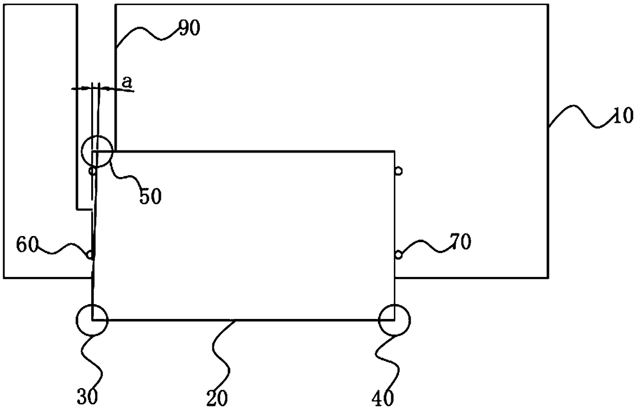
[0004] The invention provides a polarizing plate sticking device to solve the technical problem that the existing polarizing plate sticking machine cannot recognize the small bevel angle of the polarizing plate cutting, resulting in poor sticking accuracy, and the invention can solve this problem

Method used


Image

  • Polarizer attaching device
  • Polarizer attaching device

Examples


Embodiment Construction

[0026] The following descriptions of the various embodiments refer to the accompanying drawings to illustrate specific embodiments in which the invention may be practiced. The directional terms mentioned in the present invention, such as [top], [bottom], [front], [back], [left], [right], [inside], [outside], [side], etc., are only for reference The orientation of the attached schema. Therefore, the directional terms used are used to illustrate and understand the present invention, but not to limit the present invention. In the figures, structurally similar elements are denoted by the same reference numerals.

[0027] The present invention is aimed at the existing polarizing plate sticking device. When the cutting angle of the polarizing plate is not 90°, resulting in a non-rectangular shape of the polarizing plate, the existing polarizing plate sticking machine cannot recognize the small size of the polarizing plate cut. Bevel angle, thus leading to the technical problem of ...


PUM


Abstract

The invention provides a polarizer attaching device. The polarizer attacking device comprises a device platform, an image sensor component and an aligning mechanism, wherein the image sensor componentcomprises a first sensor and a second sensor located at a transverse side of the first sensor, and the first sensor and the second sensor are located on the same straight line; the aligning mechanismcomprises a first aligning component located at a longitudinal side of the first sensor and a second aligning component located at the longitudinal side of the second sensor; the image sensor component further comprise a third sensor located at the longitudinal side of the first sensor. The polarizer attaching device has the beneficial effects of converting a small oblique angle into linear gap,thereby recognizing the small oblique angle by the image sensors, solving a problem that attaching accuracy is influenced by cutting accuracy of the polarizer, reducing factors influencing the attaching accuracy, enabling the attaching accuracy to be more steady, making attaching more accurate, meanwhile, also being capable of performing early warning if cutting of the polarizer exceeds made specifications, and reducing a rate of reworking.

Description

technical field [0001] The invention relates to the technical field of display panel manufacturing, in particular to a polarizing plate pasting device. Background technique [0002] With the development of display technology, liquid crystal display technology has become the mainstream of the display panel manufacturing industry. In the display panel manufacturing industry, liquid crystal displays include a liquid crystal panel formed by pairing a color filter substrate and an array substrate. After the liquid crystal panel is formed, it needs to be mechanically cut and polarized. [0003] At present, the attaching accuracy of the polarizing plate attaching machine is greatly affected by the cutting of the polarizing plate. The existing machine uses two image sensors (Charge-coupled Device, CCD) for alignment. When the cutting angle of the polarizing plate is not At 90°, when the shape of the polarizing plate becomes non-rectangular, the existing polarizing plate attaching m...

Claims


Application Information

Patent Timeline
IPC IPC(8): G02F1/13G02F1/1335
CPCG02F1/1303G02F1/133528
Inventor 叶城飞
Owner SHENZHEN CHINA STAR OPTOELECTRONICS SEMICON DISPLAY TECH CO LTD
Learn More