
High-precision optical-mechanical accelerometer based on hemispherical micro-nano cavity mechanical-optical coupling

An optical coupling and accelerometer technology, which is applied in speed/acceleration/shock measurement, acceleration measurement, acceleration measurement using inertial force, etc., can solve the problem of low detection sensitivity, achieve high sensitivity, stable performance, and low uncertainty Effect

Inactive Publication Date: 2019-01-04
SOUTHEAST UNIV
View PDF4 Cites 4 Cited by
  • Summary
  • Abstract
  • Description
  • Claims
  • Application Information

AI Technical Summary

Problems solved by technology

However, with the continuous improvement of the performance requirements of the micromachined accelerometer, for inertial navigation level high precision (10 -6 -10 -9 g) The demand for the micro-accelerometer is becoming more and more urgent, while the detection sensitivity of the MOEMS accelerometer in the prior art is low and cannot meet the demand

Method used


Image

  • High-precision optical-mechanical accelerometer based on hemispherical micro-nano cavity mechanical-optical coupling
  • High-precision optical-mechanical accelerometer based on hemispherical micro-nano cavity mechanical-optical coupling
  • High-precision optical-mechanical accelerometer based on hemispherical micro-nano cavity mechanical-optical coupling

Examples


Embodiment Construction

[0030] The technical solutions provided by the present invention will be described in detail below in conjunction with specific examples. It should be understood that the following specific embodiments are only used to illustrate the present invention and are not intended to limit the scope of the present invention.

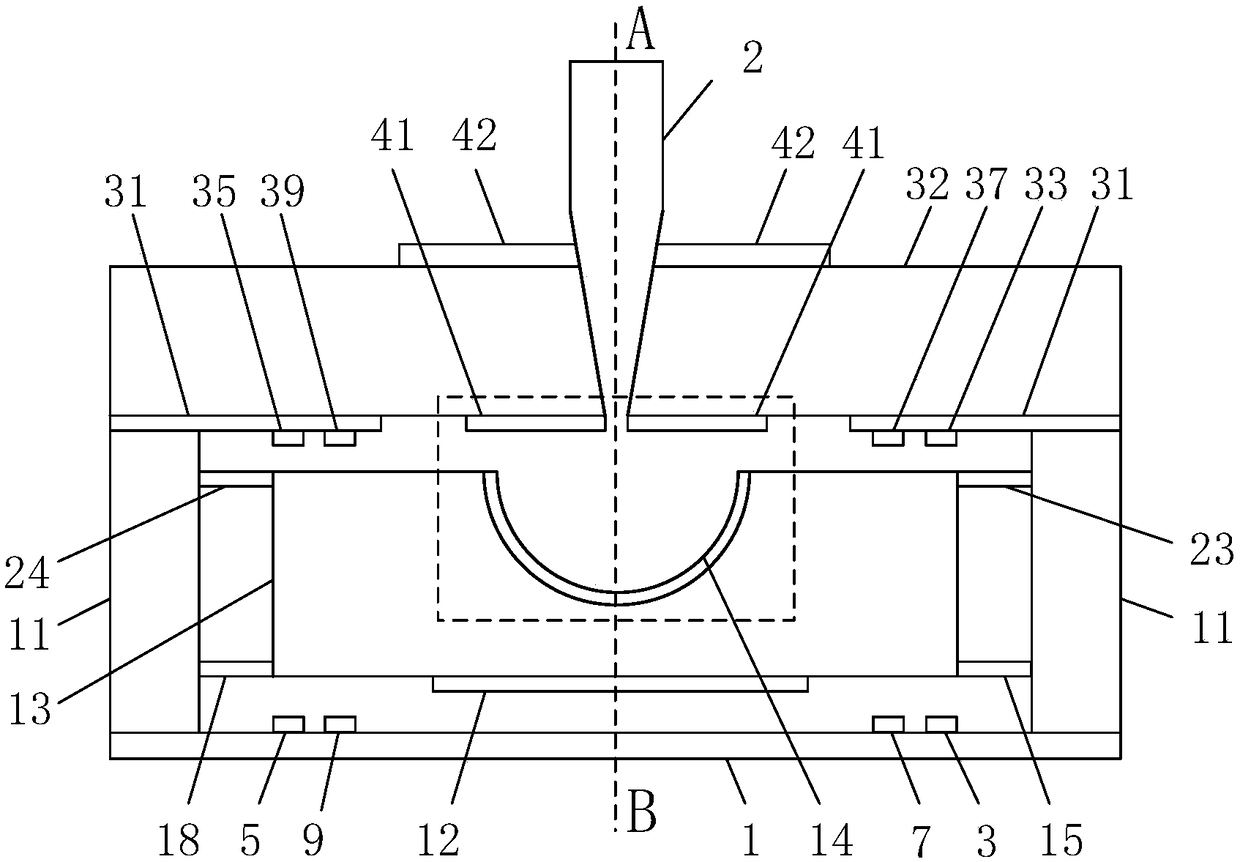
[0031] Such as figure 1 As shown, the high-precision optomechanical accelerometer based on the mechanical-optical coupling of the hemispherical micro-nano cavity proposed by the present invention consists of a three-layer structure. glass substrate. The upper structure is bonded to the middle structure through the upper end of the annular fixed anchor point 11 , and the middle structure is bonded to the lower structure through the lower end of the annular fixed anchor point 11 .

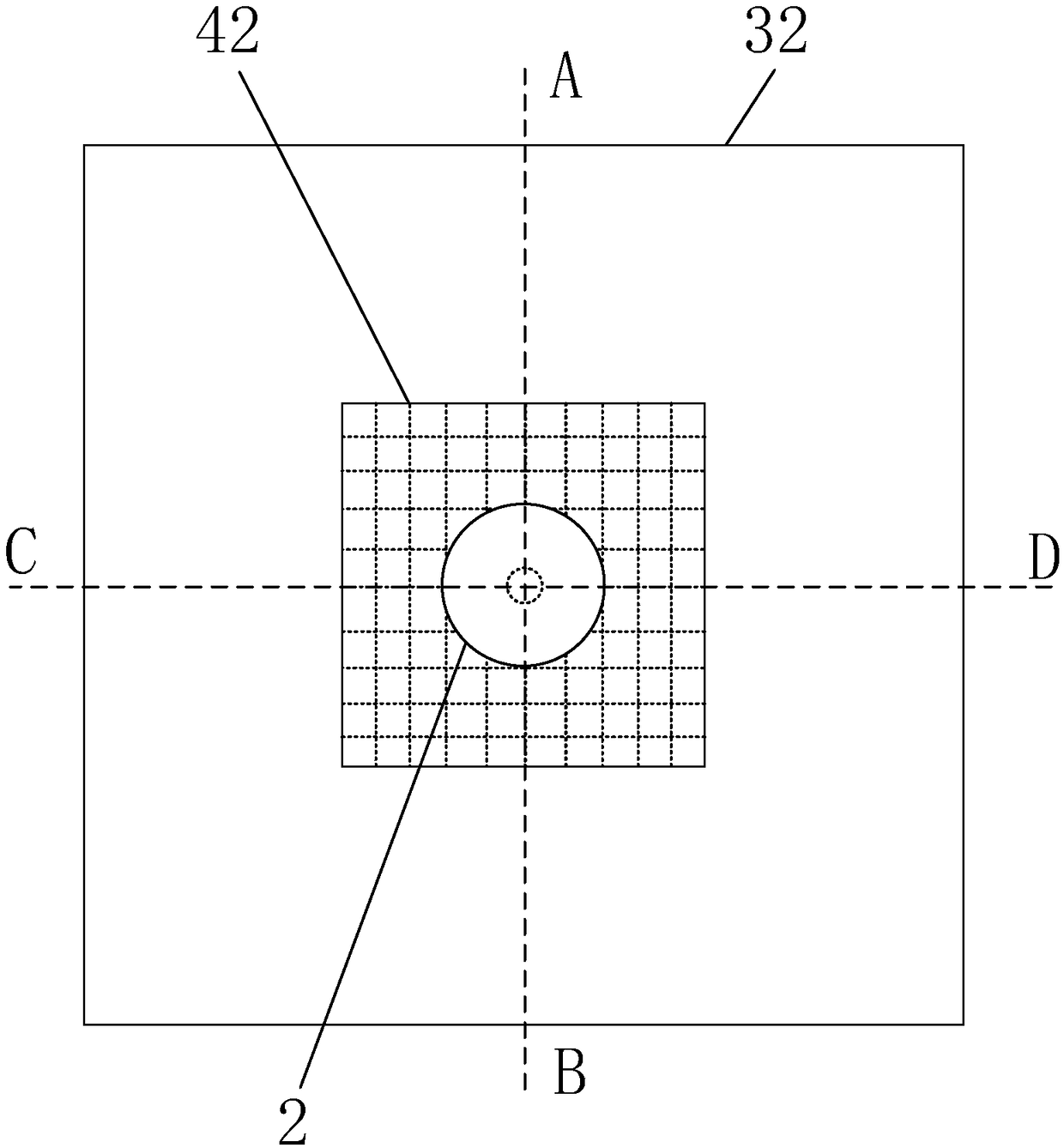
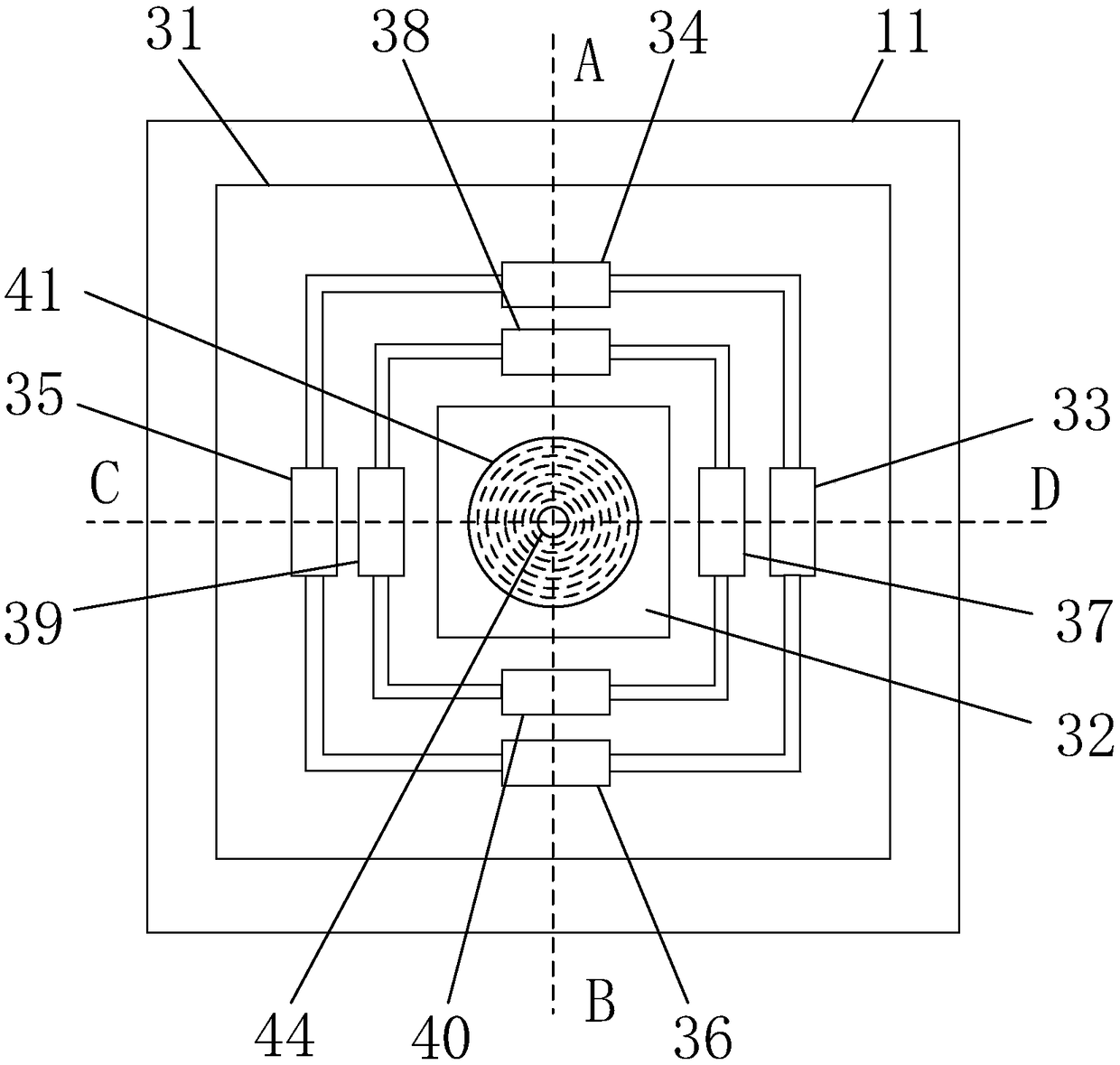
[0032] Specifically, as figure 2 , image 3 As shown, the upper structure consists of micro-nano optical fiber 2, planar cavity 32, upper anti-reflection coating 42, upper planar mi...


PUM


Abstract

The invention discloses a high-precision optical-mechanical accelerometer based on hemispherical micro-nano cavity mechanical-optical coupling. The high-precision optical-mechanical accelerometer comprises an upper planar cavity silicon microstructure, a middle hemispherical cavity silicon microstructure and a lower glass substrate with electrode leads. The upper structure is bonded on the middlestructure through the upper end of the annular fixed anchor points, and the middle structure is bonded on the lower structure through the lower end of the annular fixed anchor points. The upper structure comprises micro-nano optical fibers, a planar cavity, an upper antireflection coating layer, an upper mirror coating layer, an insulating layer, a feedback electrode and a spacing adjusting electrode. The middle structure comprises a hemispherical cavity mass, a lower antireflection coating layer, a lower hemispherical mirror coating layer, the annular fixed anchor points and multiple elasticcantilever beams. The lower structure comprises a feedback electrode, a spacing adjusting electrode, a signal lead and the glass substrate. The optical signal is used as the measuring signal of the micro accelerometer and the hemispherical optical micro-nano cavity is used so that the sensitivity is high and the dynamic range is large.

Description

technical field [0001] The invention belongs to the technical fields of micro-opto-electromechanical systems and micro-inertial measurement, and relates to an accelerometer, more specifically, to a high-precision accelerometer based on hemispherical micro-nano cavity mechanical-optical coupling that can be used for out-of-plane vertical axis acceleration sensitivity. Optomechanical accelerometer. Background technique [0002] Micro-opto-electro-mechanical system (MOEMS) is a very dynamic new technology system developed in micro-electro-mechanical system (MEMS) in recent years. It is a combination of micro-optics, micro-electronics and micro-mechanics. The new micro-optical structure system can give full play to the comprehensive performance of the three. Compared with conventional systems, micro-opto-electromechanical systems have significant advantages such as small size, light weight, compatibility with large-scale integrated circuit manufacturing processes, easy mass pro...

Claims


Application Information

Patent Timeline
IPC IPC(8): G01P15/093G01P15/097G01P15/13G01P15/08
CPCG01P15/08G01P15/093G01P15/097G01P15/131G01P2015/0862
Inventor 杨波郭鑫李成
Owner SOUTHEAST UNIV
Learn More