
Hardware polishing machine capable of preventing eye injury

A polishing machine and hardware technology, used in grinding/polishing equipment, grinding/polishing safety devices, grinding machines, etc., can solve problems such as not being able to prevent operator eye damage, improve heat dissipation, avoid The effect of the device falling off and improving the usability

Inactive Publication Date: 2019-01-04
安徽省艺馨家私有限公司
View PDF8 Cites 2 Cited by
  • Summary
  • Abstract
  • Description
  • Claims
  • Application Information

AI Technical Summary

Problems solved by technology

[0003] The object of the present invention is to provide a metal grinder that prevents eye damage, so as to solve the problem that the existing hardware grinder proposed in the background technology cannot prevent the operator's eye damage well

Method used


Image

  • Hardware polishing machine capable of preventing eye injury
  • Hardware polishing machine capable of preventing eye injury
  • Hardware polishing machine capable of preventing eye injury

Examples


Embodiment 1

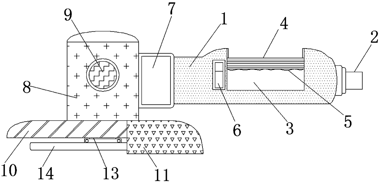
[0020] Example 1, such as figure 1 , 2 Or as shown in 3, first put your hand into the groove 3, and then hold the first anti-slip stripe grip 4, under the anti-slip effect of the first anti-slip stripe grip 4 and the rubber protrusion 5, the operator can move steadily Holding the device prevents the device from falling off during operation, causing accidental injury or causing damage to the device, thereby improving the practicability of the device.

[0021] The grip end 1 is provided with an operation button 6, the left side of the grip end 1 is fixed with a connection block 7, and the left side of the connection block 7 is fixed with a grinding end 8, and the front of the grinding end 8 is fixed with a second non-slip stripe grip bar 9, and the left side of the grinding end 8 below the second anti-skid stripe grip 9 is fixed with a first catch 10, by holding the second anti-skid stripe grip 9 with the other hand, the second anti-skid stripe grip 9 Under the action, the ope...

Embodiment 2

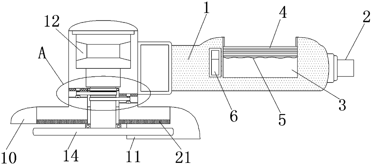
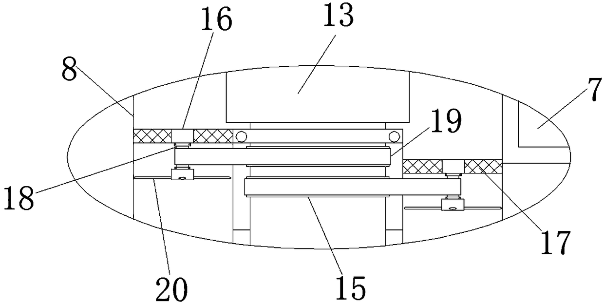
[0024] Example 2, such as figure 1 , 2 , 3 or 4, first connect the external power supply interface 2 to an external power supply to provide power for the device, and then operate the device through the operation button 6. A control chip is arranged inside the operation button 6, and the control chip controls the built-in motor through the operation button 6. 12 rotates, and the built-in motor 12 rotates to drive the output shaft 13 and the grinding sheet 14 to rotate, thereby performing the grinding operation. It will drive the driven shaft 18 and the fan blades 20 to rotate accordingly. Since the speed is very fast, the speed of the fan blades 20 is also very fast, which makes the heat generated by the built-in motor 12 work to be sucked out through the filter screen 17, and then through the through hole 21 discharge, plus the length of the grinding end 8 is less than the length of the grinding sheet 14, so the discharged wind will evenly blow out the debris produced during ...


PUM


Abstract

The invention discloses a hardware polishing machine capable of preventing eye injury. The machine comprises a holding end, a groove, a first antiskid stripe holding rod and a first baffle plate; an external power supply interface is arranged at the right end of the holding end; an operation button is arranged on the holding end; a connecting block is fixed on the left side of the holding end; a polishing end is fixed on the left side of the connecting block; a second antiskid stripe holding rod is fixed on the front surface of the polishing end; the first baffle plate is fixed on the left side of the polishing end under the second antiskid stripe holding rod; a second baffle plate is fixed on the right side of the polishing end under the second antiskid stripe holding rod; and an internalmotor is fixed at the top end in the polishing end. Through arrangement of the first baffle plate, the second baffle plate, the internal motor, an output shaft, a polishing piece, a driving shaft, afixed plate, a filter screen, a driven shaft, a belt, fan blades and through holes, the hardware polishing machine capable of preventing eye injury can preferably prevent the eye and hand injury of operators to improve the safety.

Description

technical field [0001] The invention relates to the technical field of polishing machines, in particular to a hardware polishing machine for preventing eye damage. Background technique [0002] Existing metal grinders will generate a lot of sparks when grinding, and these sparks are uncontrollable and will splash everywhere. They may splash on the operator's hands, cause burns, or splash into the operator's eyes. In severe cases, it will cause irreversible damage and reduce the safety of the device. For this, people generally operate by wearing gloves or goggles, but this situation is more troublesome. Protective equipment needs to be prepared earlier, which reduces the working efficiency of the device. Therefore, a metal polisher that prevents eye damage is urgently needed to solve the above problems. Contents of the invention [0003] The object of the present invention is to provide a metal grinder that prevents eye damage, so as to solve the problem that the existing ...

Claims


Application Information

Patent Timeline
Patent Type & Authority Applications(China)
IPC IPC(8): B24B23/02B24B55/05B24B55/02
CPCB24B23/005B24B23/02B24B55/02B24B55/045B24B55/052
Inventor 傅克强
Owner 安徽省艺馨家私有限公司
Learn More