Method for producing a piston for a combustion engine from a piston upper part and a piston lower part

An internal combustion engine, piston technology, applied in the direction of pistons, mechanical equipment, engine components, etc., to prevent overheating

Active Publication Date: 2019-01-04
MAHLE INT GMBH
View PDF11 Cites 0 Cited by
  • Summary
  • Abstract
  • Description
  • Claims
  • Application Information

AI Technical Summary

Problems solved by technology

[0003] However, it often proves disadvantageous that the weld seams that usually occur during friction welding form in the area of ​​the piston, especially in the inner shape of the piston below the piston recess, and these areas must actually remain free for use. in link movement

Method used


Image

  • Method for producing a piston for a combustion engine from a piston upper part and a piston lower part
  • Method for producing a piston for a combustion engine from a piston upper part and a piston lower part

Examples


Embodiment Construction

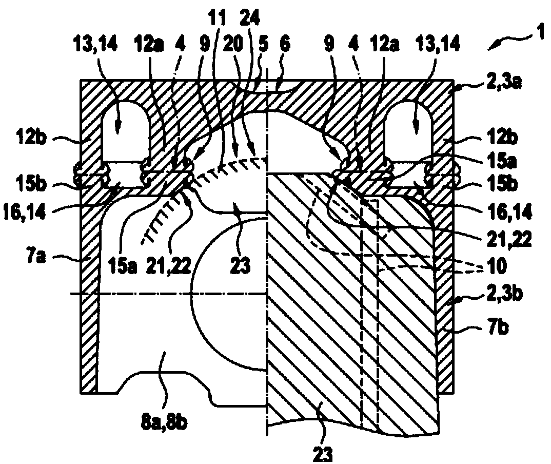
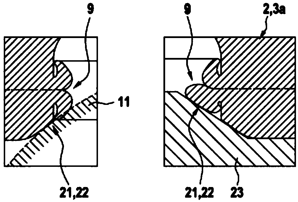
[0026] figure 1 and figure 2 An example of a friction welding device 1 according to the invention for producing a piston 2 for an internal combustion engine consisting of a piston upper part 3 a and a piston lower part 3 b each made of steel is shown. The friction welding device 1 is used to join the piston upper part 3a and the piston lower part 3b by friction welding. The friction welding device 1 comprises a clamping device 23 (only partially shown in the figure) in which the upper piston part 3a and the lower piston part 3b can be clamped for friction welding. A more precise technical design of the friction welding device 1 is known to those skilled in the relevant art, so a more detailed explanation will be omitted below.

[0027] The piston upper part 3 a comprises a piston head 5 with a combustion recess 6 . The piston lower part 3b has two mutually opposite skirt elements 7a, 7b which are connected to one another via two mutually opposite pin seats 8a, 8b. The pis...


PUM


Abstract

A method for producing a piston (2) for an internal combustion engine may include arranging a piston upper part (3a) and a piston lower part (3b) in a friction welding device. The piston upper part (3a) may include a piston head with a combustion recess. The piston lower part may include two mutually opposite skirt elements connected to one another via two mutually opposite pin bosses. The methodmay also include arranging a deflecting device configured to deflect at least one weld bead one of on and in the friction welding device. The method may further include joining the piston upper part (3a) and the piston lower part (3b) to one another via friction welding.

Description

technical field [0001] The invention relates to a method for producing a piston for an internal combustion engine consisting of a piston upper part and a piston lower part. The invention also relates to a friction welding device designed to carry out the method. Background technique [0002] It is known from the prior art that, for assembling the piston, the piston upper part and the piston lower part can be fastened to each other by friction welding. [0003] However, it often proves disadvantageous that the weld seams that usually occur during friction welding form in the area of ​​the piston, especially in the inner shape of the piston below the piston recess, and these areas must actually remain free for use. in the linkage movement. Contents of the invention [0004] It is therefore the object of the present invention to provide an improved embodiment of the production method for a piston upper part or a piston lower part, in which the above-mentioned disadvantages ...

Claims


Application Information

Patent Timeline
IPC IPC(8): B23K20/12F02F3/00
CPCB23K20/1245B23K20/129F02F3/003F02F2003/0061F02F3/22B23K2101/003B23K33/006B23K33/008
Inventor 彼得·温克勒
Owner MAHLE INT GMBH
Why Eureka
Try Eureka