
Improved structure of full casing spiral drilling machine and full casing threaded filling pile construction method

An auger drilling rig and structure-improving technology, which is applied to rotary drilling rigs, infrastructure engineering, drilling equipment and methods, etc., can solve the problems of secondary reaming, inability to improve the resistance of cast-in-place piles, and increase of end resistance of cast-in-place piles. , to achieve the effect of thread space rules, reducing drilling difficulty and stable quality

Pending Publication Date: 2019-01-01
刘淼
View PDF4 Cites 10 Cited by
  • Summary
  • Abstract
  • Description
  • Claims
  • Application Information

AI Technical Summary

Problems solved by technology

Although the existing full-sleeve rotary drilling machine and pile-forming method overcome many difficulties in the construction of large-diameter cast-in-place piles, the large-diameter cast-in-place piles formed are all straight-line cast-in-situ piles with equal cross-sections, and it is impossible to form concrete through the pile body. The screw tooth improves the measured resistance of the cast-in-place pile, and it is impossible to re-expand holes in the hard soil layer and rock layer at the bottom of the pile. By increasing the area of ​​the pile bottom, the resistance at the end of the cast-in-place pile is increased, thereby further improving the vertical bearing capacity of the cast-in-place pile.

Method used


Image

  • Improved structure of full casing spiral drilling machine and full casing threaded filling pile construction method
  • Improved structure of full casing spiral drilling machine and full casing threaded filling pile construction method
  • Improved structure of full casing spiral drilling machine and full casing threaded filling pile construction method

Examples


Embodiment Construction

[0047] The following will clearly and completely describe the technical solutions in the embodiments of the present invention with reference to the accompanying drawings in the embodiments of the present invention. Obviously, the described embodiments are only some, not all, embodiments of the present invention. Based on the embodiments of the present invention, all other embodiments obtained by persons of ordinary skill in the art without making creative efforts belong to the protection scope of the present invention.

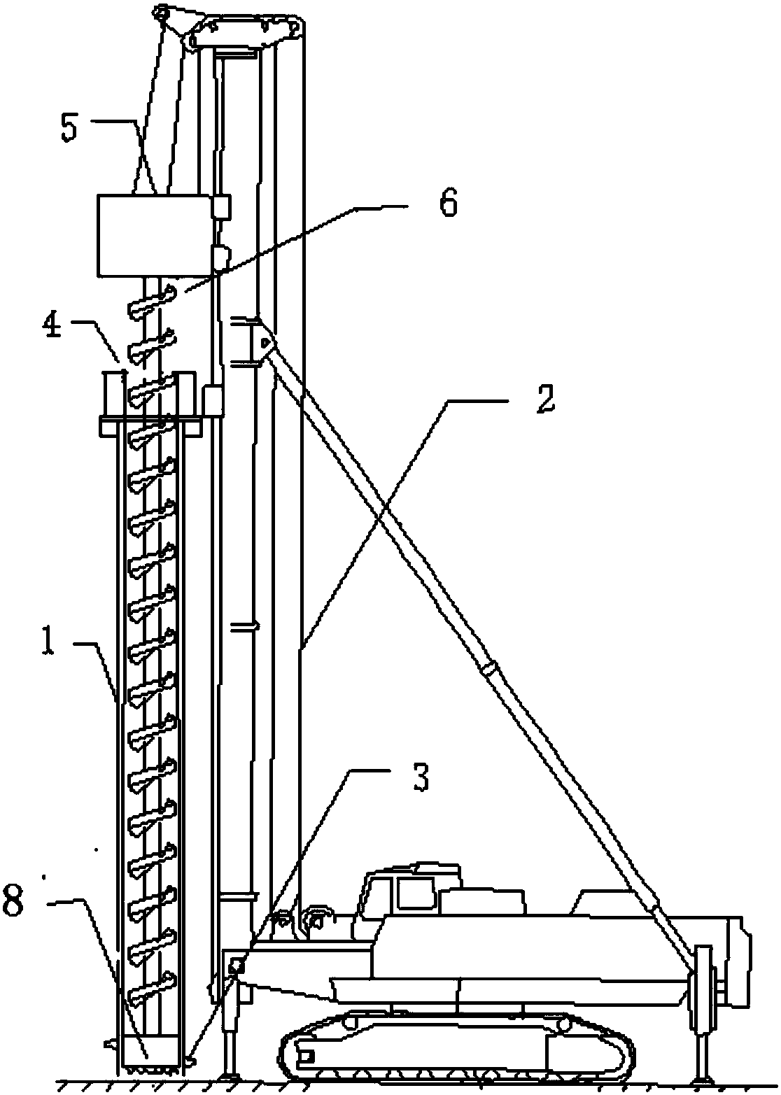
[0048] Such as figure 1 Shown: an improved structure of a full casing auger drill, including a double power head auger 2, a casing 1 is installed on the double power head auger 2, and a detachable installation on the casing 1 can make it rotate The lower power head 4, the upper part of the lower power head 4 is provided with an upper power head 5;

[0049] The upper power head 5 is detachably connected with an auger rod 6 that can move up and down in the casi...


PUM


Abstract

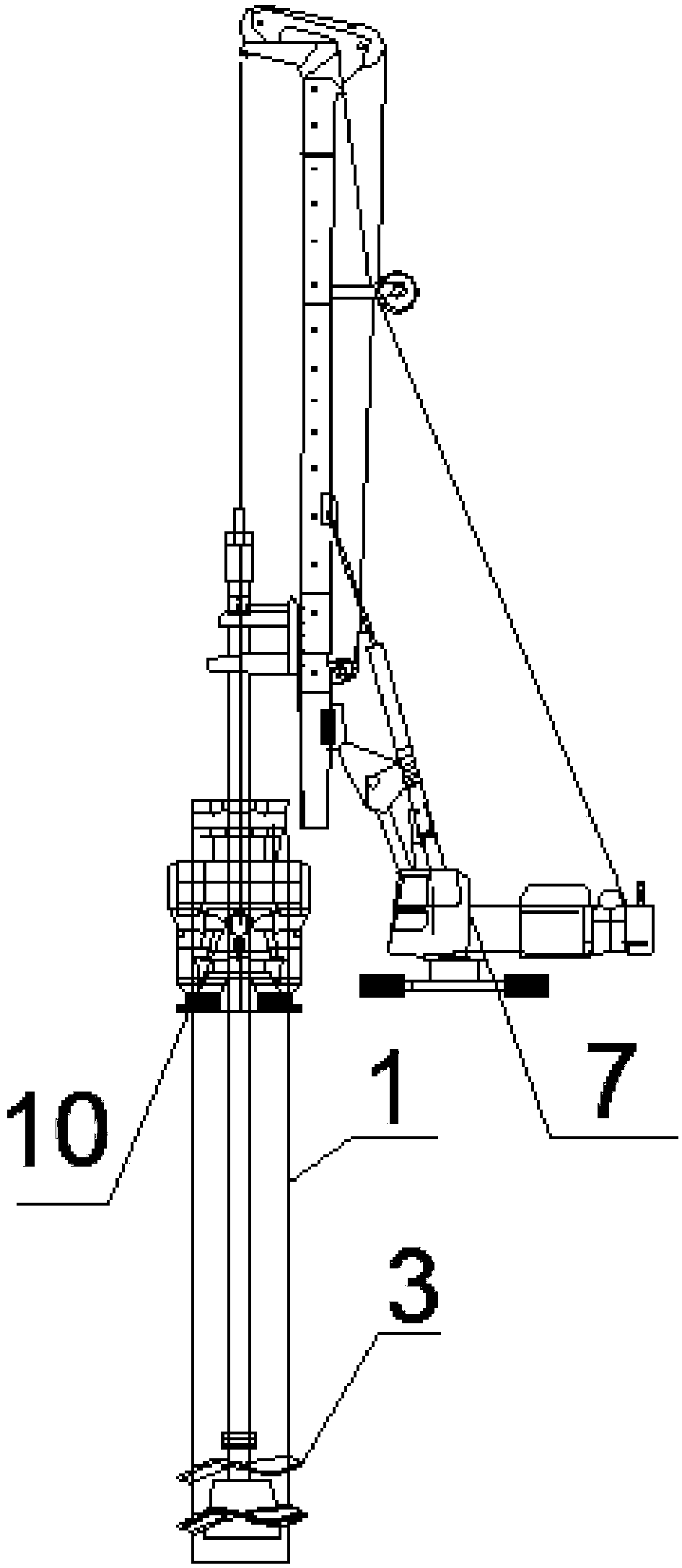
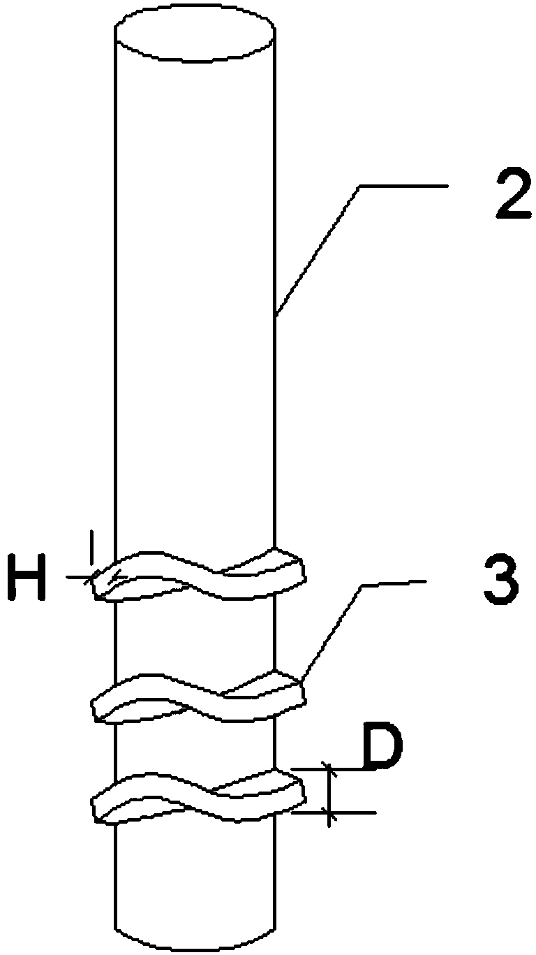
The invention discloses an improved structure of a full casing spiral drilling machine and a full casing threaded filling pile construction method. The improved structure of the full casing spiral drilling machine includes a double power head spiral drilling machine (2). A casing (1) is mounted on the double power head spiral drilling machine (2). A lower power head (4) capable of making the sleeve tube rotate is detachably mounted on the casing. An upper power head (5) is arranged above the lower power head. A spiral drilling rod (6) capable of moving up and down in the casing is detachably connected to the upper power head. A drilling device capable of moving in the casing is connected to the lower end of the spiral drilling rod. A spiral member (3) is integrally formed on at least a part of the outer wall of the casing, wherein the spiral direction of the spiral member is opposite to that of the spiral drilling rod. The drilling machine improvement is simple and durable. the full casing spiral drilling machine with the structure and the construction method of the invention can be used to form threaded piles with medium and large diameter under conventional mechanical equipment dynamic conditions, and so threaded special-shaped piles are more in line with increasing demand of pile bearing capacity for structures at a current stage.

Description

technical field [0001] The invention relates to an improved structure and a construction method of a pile, in particular to an improved structure of a full casing auger drilling machine and a construction method of a full casing threaded cast-in-place pile, belonging to the technical field of construction engineering. Background technique [0002] With the development of society, land resources are scarce, and buildings are gradually developing to high-rise buildings. The load of buildings and structures is increasing, so that pile types with higher bearing capacity, pile-forming methods and pile-forming machinery are widely used in foundation engineering, among which various threaded cast-in-situ piles with medium diameters and large-diameter cast-in-place piles are widely used in foundation engineering. The application is particularly extensive. [0003] The research on threaded cast-in-situ piles in our country was carried out in the 1990s, and a variety of pile types an...

Claims


Application Information

Patent Timeline
IPC IPC(8): E21B3/00E21B17/22E21B4/16E21B7/28E02D5/38E02D5/56
CPCE21B3/00E21B4/16E21B7/28E21B17/22E02D5/385E02D5/56
Inventor 刘淼
Owner 刘淼
Learn More