
Control of permanent magnet motors and generators

A technology of permanent magnet motor and permanent magnet generator, which is applied in the direction of AC motor control, electronic commutation motor control, single motor speed/torque control, etc., and can solve the problems of high cost and complexity of electronic components

Active Publication Date: 2018-12-28
AERISTECH
View PDF4 Cites 0 Cited by
  • Summary
  • Abstract
  • Description
  • Claims
  • Application Information

AI Technical Summary

Problems solved by technology

This means high cost and complexity of electronic components

Method used


Image

  • Control of permanent magnet motors and generators
  • Control of permanent magnet motors and generators
  • Control of permanent magnet motors and generators

Examples


Embodiment Construction

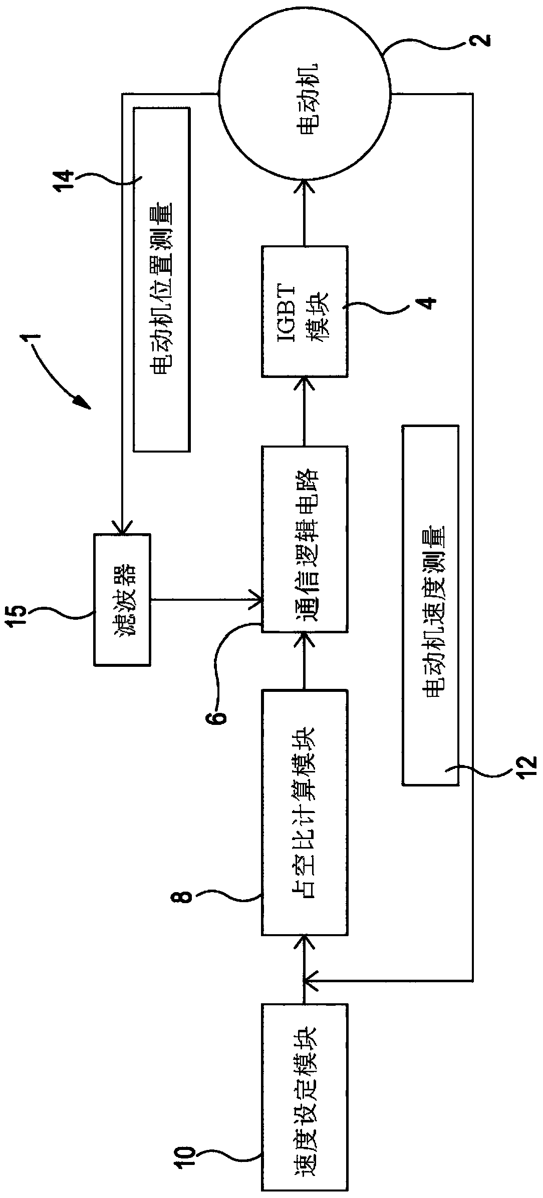
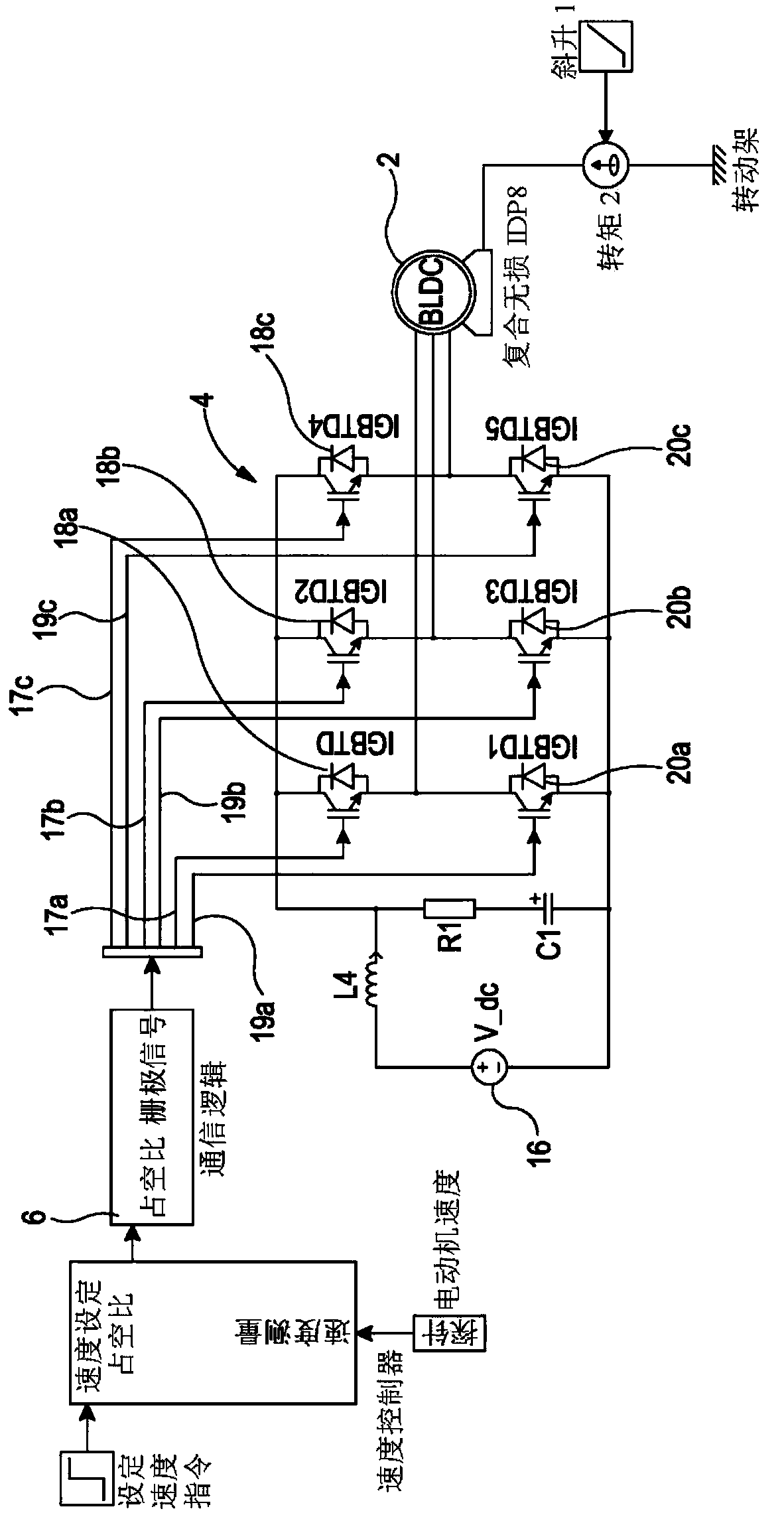
[0042] refer to figure 1 , shows a schematic diagram of a brushless DC motor controller 1, which includes a brushless DC motor 2, an integrated gate bipolar transistor (IGBT) module 4, a commutation logic circuit 6, a duty ratio calculation module 8, a speed setting Module 10 and feedback loops for motor speed measurement 12 and for motor position measurement 14 . The feedback loop for motor position measurement 14 includes a filter 15 .

[0043] The desired motor speed 10 is compared to the rotor speed measurement 12, which is used to perform a duty cycle calculation 8 to determine the required motor current. The commutation logic 6 determines which stator windings require current based on filtered motor position measurements 14 , which in this case come from measurements of the motor emf. The calculated duty cycle and commutation signals are fed into the motor controller 4 which ensures that the correct current flows through the correct windings of the motor 2 . The funct...


PUM


Abstract

A permanent magnet motor (2), and also a permanent magnet generator (102) comprising a plurality of phase windings, a control system (16) and a commutation circuit (6) is described. The commutation circuit (6) is operative for controlling a timing of a current supplied to the phase windings in dependence upon an angular position of the permanent magnet motor (2). The control system (16) is operative to supply a current to an individual of the phase windings in a current pulse event occurring within a commutation event. The duration of the current pulse event is less than the duration of the commutation event and the proportion of the commutation event for which the current is supplied to the individual of the phase windings is determined so as to control the speed of the motor (2).

Description

technical field [0001] The invention relates to a permanent magnet motor with a control system and a commutation circuit, and a permanent magnet generator with a control system and a commutation circuit. Background technique [0002] A permanent magnet motor includes a permanent magnet rotor and a stator with windings. A permanent magnet rotor includes a plurality of pole pairs. Electrical energy is converted into mechanical energy due to the magnetic force between the permanent magnets and the magnetic field due to the current flow in the stator windings. [0003] As the permanent magnets rotate, their position changes relative to the fixed winding. This means that current needs to flow through different windings at different points in the rotation cycle. Electronic commutation provides a means to ensure that current is delivered to the correct stator windings at the correct time to produce maximum torque on the rotor. This requires either a means of sensing the rotor p...

Claims


Application Information

Patent Timeline
Patent Type & Authority Applications(China)
IPC IPC(8): H02P6/06H02P6/28H02K21/12H02P6/15H02P25/03H02P6/16
CPCH02P6/16H02P6/157H02P6/28H02P25/03H02K21/12H02P6/06
Inventor B·G·R·理查德斯M·卡尔巴切克
Owner AERISTECH
Learn More