A modeling method of three-dimensional finite element model

A modeling method and finite element technology, applied in the modeling field of 3D finite element model, can solve the problem of unguaranteed mesh quality, and achieve the effect of saving modeling time, improving mesh quality, and ensuring mesh quality.

Active Publication Date: 2018-12-28
CHINA THREE GORGES UNIV
View PDF6 Cites 11 Cited by
  • Summary
  • Abstract
  • Description
  • Claims
  • Application Information

AI Technical Summary

Problems solved by technology

The conventional modeling method is to directly establish a three-dimensional geometric model according to the physical structure of the object. Taking the electromagnetic rail gun as an example, the three-dimensional models of the guide rail, armature and...

Method used


Image

  • A modeling method of three-dimensional finite element model
  • A modeling method of three-dimensional finite element model
  • A modeling method of three-dimensional finite element model

Examples


Embodiment 1

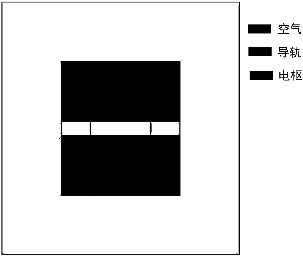
[0040] Taking the electromagnetic railgun as an example, the schematic diagram of the double-layer electromagnetic railgun is as follows figure 1 As shown, the three-dimensional entity of the double-layer electromagnetic railgun includes two upper rails 1, two lower rails 2, an upper armature 3, and a lower armature 4, wherein the rails are made of copper and the armature is made of aluminum. In this object entity, the upper guide rail 1 and the lower guide rail 2 have a plane symmetrical structure, and the long side direction is zThe axial direction is the axial direction of plane symmetry, and the upper layer armature 3 and the lower layer armature 4 are located in different positions due to different speeds of movement. In this calculation example, it is assumed that the vertical position of the upper layer armature is in the front, and the lower layer armature is behind, and The positions of the two overlap partially in the vertical direction. In addition, in the finite e...

Embodiment 2

[0047] The cable tunnel in the project is shown as Figure 11 As shown, the structural characteristics of the entity object are: power cables with different voltage levels and different arrangements; and cable line supports, as well as tunnel concrete walls and air in the tunnel. Along the cable and tunnel extension direction is z axis, where the power cables and tunnel walls and the air area are z The planar symmetric structure in the axial direction, but there is one support at a certain distance, which is not a planar symmetric structure. Take the cable tunnel as an example to describe the implementation process:

[0048] (1): Establish two-dimensional models of power cable sections, brackets, tunnel walls, and air areas with different voltage levels and different arrangements, such as Figure 12 shown.

[0049] (2): Divide the two-dimensional model into finite elements using triangular meshes, such as Figure 13 As shown, a two-dimensional finite element model is gene...


PUM


Abstract

The invention discloses a method for modeling a three-dimensional finite element model. In accordance with a similar electromagnetic rail gun, a three-phase bus slot, such as power cable lines and tunnels, a 3-D entity with a planar symmetrical structure feature that that object is the main object is involved. In establishing the finite element model, first, a two-dimensional plane model is established, and then the finite element is divided into triangular meshes, the two-dimensional finite element model is stretched along the plane symmetry axis, at the different position of each main body object in the three-dimensional entity, the starting point of the segment stretch is determined, and the mesh is also divided in the axial direction during the stretching process, as the three-dimensional geometric model is formed, the corresponding three-dimensional finite element model is generated simultaneously, the finite element model generated by stretching is triangular prismatic mesh, andits mesh quality is better than that of tetrahedral mesh, which not only saves modeling time, but also ensures the mesh quality, and provides a new idea for the modeling method of three-dimensional finite element model of electromagnetic field numerical computation.

Description

technical field [0001] The invention relates to a modeling method of a three-dimensional finite element model, which relates to the technical fields of electromagnetic field numerical calculation and electrical theory. Background technique [0002] For research objects such as electromagnetic railguns, three-phase bus ducts, and power cable tunnels, the three-dimensional entity features are: they all contain entities with plane symmetrical structures such as guide rails, bus bars, and cables; while armatures and line supports are not Planar symmetrical structure. When carrying out finite element numerical calculation of three-dimensional electromagnetic field, the three-dimensional geometric model and the finite element model of the entity must be established first, and then the numerical solution of the finite element equation can be carried out. The conventional modeling method is to directly establish a three-dimensional geometric model according to the physical structur...

Claims


Application Information

Patent Timeline
IPC IPC(8): G06T17/20G06F17/50
CPCG06T17/20G06F30/17
Inventor 黄雄峰范虹兴张宇娇苏攀智李姜岚
Owner CHINA THREE GORGES UNIV
Why Eureka
Try Eureka