
Intelligent forecast-based maximum power point tracing method of photovoltaic multi-peak value

A maximum power point, intelligent prediction technology, applied in photovoltaic power generation, renewable energy integration, instruments, etc., can solve the problems of high cost of photovoltaic cells, high hardware requirements, tracking failure, etc., to improve photovoltaic power generation efficiency, stable steady state The effect of stable power output and power generation efficiency

Active Publication Date: 2018-12-28
SHANGHAI UNIVERSITY OF ELECTRIC POWER
View PDF4 Cites 6 Cited by
  • Summary
  • Abstract
  • Description
  • Claims
  • Application Information

AI Technical Summary

Problems solved by technology

[0004] (1) The cost of photovoltaic cells is high;
[0005] (2) The photoelectric conversion efficiency is low;
[0006] (3) The hazards of partial occlusion
However, intelligent algorithms often have the disadvantages of many control parameters, complex control ideas, and high requirements for hardware, which restricts the engineering practice application of these algorithms to a certain extent, and as the operating environment of photovoltaic arrays becomes more and more complex, Due to the shading of buildings, trees or dust, it often happens that the surface of the photovoltaic array receives uneven light intensity. At this time, the power-voltage characteristic curve of the photovoltaic array will have multiple peaks.
Some intelligent algorithms, like the traditional maximum power tracking method, lack the ability of global optimization, and are only suitable for single-peak maximum power tracking systems. When tracking multi-peak systems, it will cause tracking failure

Method used


Image

  • Intelligent forecast-based maximum power point tracing method of photovoltaic multi-peak value
  • Intelligent forecast-based maximum power point tracing method of photovoltaic multi-peak value
  • Intelligent forecast-based maximum power point tracing method of photovoltaic multi-peak value

Examples


Embodiment Construction

[0059] The present invention will be described in detail below in conjunction with the accompanying drawings and specific embodiments.

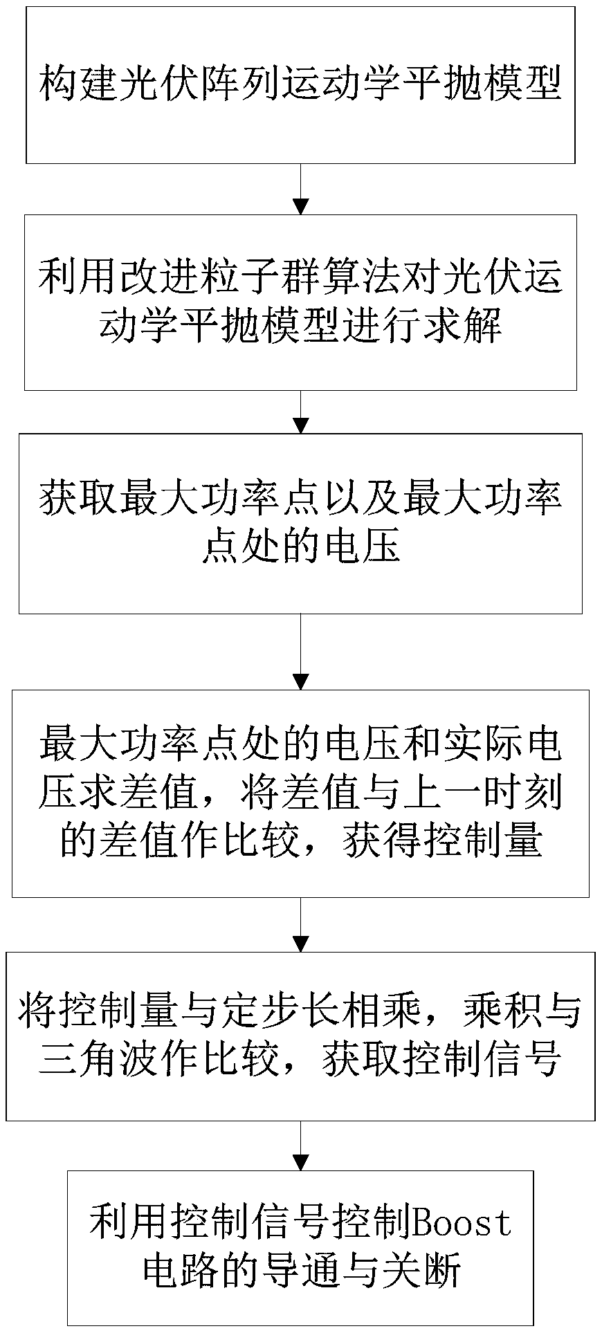
[0060] The invention relates to a photovoltaic multi-peak maximum power point tracking method based on intelligent prediction, such as figure 1 As shown, the method includes the following steps:

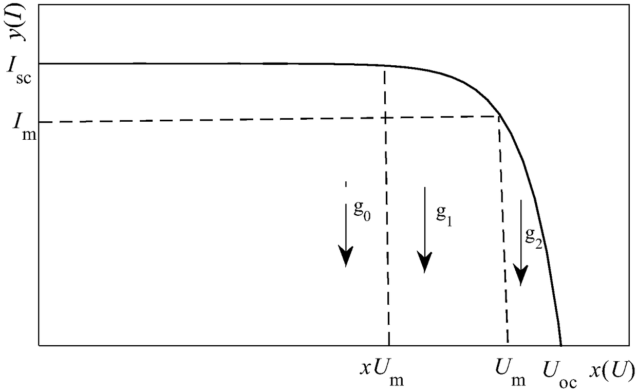
[0061] Step 1. Combining the similarity between the I-U characteristic curve of the photovoltaic array and the trajectory of the particle flat throwing, a kinematic flat throwing model of the photovoltaic array is constructed. The kinematic flat throw model of the photovoltaic array can model the photovoltaic array under any environmental conditions of light or temperature, and can realize calculation correction when the environment changes.

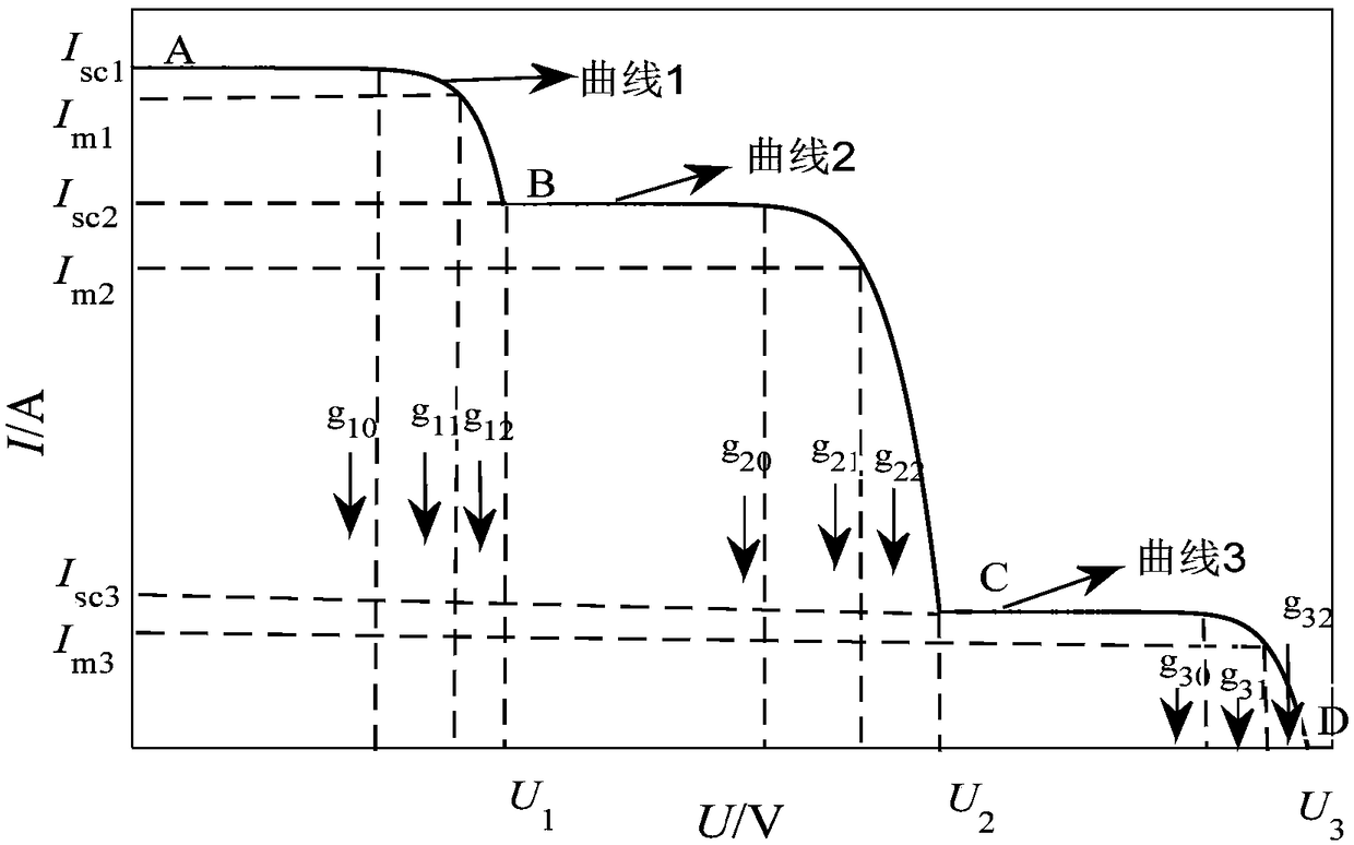
[0062] As shown in Figure 2(a), where Figure 2(a) is a schematic diagram of a single peak, and Figure 2(b) is a schematic diagram of a multi-peak time. The abscissa U is regarded as the movement time of the ...


PUM


Abstract

The invention relates to an intelligent forecast-based maximum power point tracing method of a photovoltaic multi-peak value. The intelligent forecasting-based maximum power point tracing method comprises the following steps of S1, building a photovoltaic array kinematic horizontal-projectile model by combining similarity of a photovoltaic array current-voltage characteristic curve and mass pointhorizontal-projectile motion track; S2, solving the photovoltaic array kinematic horizontal-projectile model by employing an improved particle swarm optimization method to achieve maximum power forecast (intelligent forecast), and acquiring the maximum power point and a voltage of the maximum power point; S3, fitting the photovoltaic array current-voltage characteristic curve by the photovoltaic kinematic horizontal-projectile model, and locally tracing the maximum power point by employing a voltage closed-loop control method after forecast to acquire a control signal, wherein the fitting might not be accurate; and S4, controlling a Boost circuit to be connected and disconnected by employing the acquired control signal, and achieving real-time control of the photovoltaic array maximum output power. Compared with the prior art, the intelligent forecasting-based maximum power point tracing method has the advantages of global optimization of the maximum power point and the like, and the efficiency of a photovoltaic power generation system is improved.

Description

technical field [0001] The invention relates to the technical field of photovoltaic power generation, in particular to a photovoltaic multi-peak maximum power point tracking method based on intelligent prediction. Background technique [0002] Energy plays an extremely important role in creating new opportunities and promoting economic growth, while the development of the world economy and population growth in turn contribute to the world's energy demand. The core problems of my country's energy structure are as follows: first, the energy structure is dominated by coal, and coal accounts for more than 2 / 3 of my country's primary energy production and consumption; second, the issue of oil security is becoming more and more prominent. The degree of dependence will reach 60%, and my country's energy security, especially oil security, is becoming more and more prominent; third, soot-type pollution has brought serious problems to the ecological environment, while power, building m...

Claims


Application Information

Patent Timeline
IPC IPC(8): G05F1/67
CPCG05F1/67Y02B10/10Y02E10/56
Inventor 于艾清屠亚南
Owner SHANGHAI UNIVERSITY OF ELECTRIC POWER
Learn More