
Physically simulated gas injection-production flow control system of gas storage

A technology of control system and physical simulation, applied in the direction of flow control, control/regulation system, flow control using electrical devices, etc. It can achieve the effect of optimizing construction and injection-production operation plan, realizing data monitoring and operation automation, and complete functions

Active Publication Date: 2018-12-28
PETROCHINA CO LTD
View PDF6 Cites 7 Cited by
  • Summary
  • Abstract
  • Description
  • Claims
  • Application Information

AI Technical Summary

Problems solved by technology

During the injection-production operation of the porous gas storage, affected by many factors such as injection-production speed, operating pressure range, and water intrusion, it is impossible to simulate the reciprocating high-speed injection-production operation law and its impact on the operation of the gas storage by using conventional oil and gas reservoir development experiment methods. Influence of database construction and operation efficiency
Conventional experimental devices use mass flow controllers to realize gas injection and production. The type of gas controlled by such devices is single, and the range of gas flow and pressure controlled is limited. It is difficult to meet the large pressure range and high-speed injection and production of porous gas storage. The need for operational mechanistic studies

Method used


Image

  • Physically simulated gas injection-production flow control system of gas storage
  • Physically simulated gas injection-production flow control system of gas storage
  • Physically simulated gas injection-production flow control system of gas storage

Examples


Embodiment Construction

[0023] In order to make the purpose, technical solutions and advantages of the embodiments of the present invention more clear, the present invention will be further described in detail below in conjunction with the embodiments and the accompanying drawings. Here, the exemplary embodiments of the present invention and their descriptions are used to explain the present invention, but not to limit the present invention.

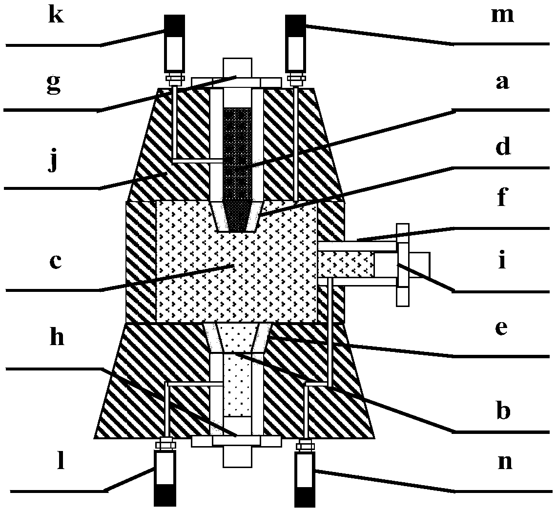
[0024] Please refer to figure 1As shown, the gas storage physical simulation injection-production gas flow control system provided by the present invention specifically includes: injection-production control devices 1, 2, gas booster devices 3, 4, gas cylinder devices 5, 6, and gas flow monitoring devices 7, 8, gas storage core model 9 and control analysis device 10; the gas injection and production control devices 1 and 2 are connected to the gas storage core model 9, and the gas injection and production control devices 1 and 2 include a high-pressure chamber ...


PUM


Abstract

The invention discloses a physically simulated gas injection-production flow control system of a gas storage. The system specifically comprises a gas injection-production control device which is connected with gas storage core model, and comprises a high-pressure cavity, a low-pressure cavity and a balance cavity; the control on the pressure and the flow of injected gas and produced gas of the gasstorage core model is realized by sufficiently mixing the gas in the high-pressure cavity and the gas in the low-pressure cavity in the balance cavity; a gas pressurizing device is communicated withthe high-pressure cavity and / or low-pressure cavity of the gas injection-production control device, and used for controlling high-pressure cavity pressure and / or the low-pressure cavity pressure in the gas injection-production control device; a gas cylinder device is connected with the gas pressurizing device and used for providing gas source for the gas pressurizing device; a gas flow monitoringdevice is arranged between the gas injection-production control device and the gas storage core model and used for recording gas flow data in the gas injection and gas production process; and a control analysis device is respectively connected with the gas pressurizing device and the gas traffic monitoring device, and used for controlling a control system to simulate the gas injection-production parameter in the actual gas storage, and monitoring and recording various experimental data.

Description

technical field [0001] The invention relates to the technical field of porous gas storage, in particular to a gas storage physical simulation gas injection and production flow control system for controlling the injection and production gas flow during the actual periodic injection and production operation of the simulated gas storage in a laboratory. Background technique [0002] Underground gas storage is mainly a pore-type gas storage rebuilt from depleted oil and gas reservoirs. Therefore, before the construction of the gas storage, it is necessary to fully understand the original physical properties of the reservoir, and study the injection-production operation mechanism of the rebuilt gas storage and its main features. Influencing factors, especially the influence of gas injection and gas production flow rates on gas storage capacity parameters during injection and production operations, to guide the optimization of gas storage injection and production operation plans. ...

Claims


Application Information

Patent Timeline
Patent Type & Authority Applications(China)
IPC IPC(8): G05D7/06
CPCG05D7/0676
Inventor 石磊郑得文丁国生王皆明朱华银武志德张敏
Owner PETROCHINA CO LTD
Learn More