
Folding schlieren apparatus and gas temperature field visualization method based on same

A gas temperature, foldable technology, used in measuring devices, instruments, scientific instruments, etc., can solve the problems of interfering airflow direction, long response time, limiting quantitative analysis, etc., to eliminate the interference of human factors, improve clarity, reduce cost effect

Inactive Publication Date: 2018-12-28
SUN YAT SEN UNIV
View PDF7 Cites 1 Cited by
  • Summary
  • Abstract
  • Description
  • Claims
  • Application Information

AI Technical Summary

Problems solved by technology

However, for conventional "Z" and linear schlieren devices, the light only passes through the test area once, and the definition of the schlieren image is not high, which limits the quantitative analysis of the experiment; the reflection optical path based on the concave mirror, the incident light path and the reflection The optical paths are not strictly coincident, and there is a problem of ghosting
[0003] At present, contact methods such as thermistor thermometers and thermocouple temperature sensors are often used to measure gas temperature in experiments, but the response time is long, and it interferes with the flow direction of the airflow, the data accuracy is not high, and the reliability is poor; The representative non-contact temperature measurement method has better accuracy, but the equipment cost is higher

Method used


Image

  • Folding schlieren apparatus and gas temperature field visualization method based on same
  • Folding schlieren apparatus and gas temperature field visualization method based on same

Examples


Embodiment

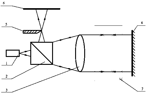
[0033] This embodiment provides a foldable schlieren device, such as figure 1 As shown, it includes a light source 1 and a beam splitter 2, a convex lens 3, and a plane mirror 4 arranged sequentially behind the light source 1; a test area 7 is set between the convex lens 3 and the plane mirror 4; After the light passes through the convex lens 3, it is converted into an optical path by the beam splitter 2, and a knife edge 5 for cutting the light beam is provided on the beam splitter 2 converted light path; an imaging device 6 for imaging the light emitted from the knife edge 5 is also included.

[0034] When using the folded schlieren device, the object to be tested is placed in the test area 7, and the light emitted by the light source 1 passes through the beam splitter 2 and the convex lens 3 to generate parallel light and passes through the test area 7, and after being reflected by the plane mirror 4 After passing through the test area 7 and the convex lens 3 again, the opt...


PUM

PropertyMeasurementUnit
diameteraaaaaaaaaa

Abstract

The invention relates to the technical field of schlieren optical imaging, in particular to a folding schlieren apparatus and a gas temperature field visualization method based on the folding schlieren apparatus. The schlieren apparatus comprises a light source as well as a beam splitter, a convex lens and a plane mirror which are sequentially arranged at the rear of the light source; a space between the convex lens and the plane mirror is used for setting a testing region; reflected light via the plane mirror is converted in light path by virtue of the beam splitter after passing through theconvex lens, and a knife edge used for cutting a light beam is arranged on a path where the beam splitter converts light; and the schlieren apparatus also comprises an imaging device used for performing imaging on light emergent from the knife edge. The light given off by the light source generates parallel light after passing through the beam splitter and the convex lens, the parallel light passes through the testing region, is reflected by the plane mirror and then respectively passes through the testing region and the convex lens, the light path is converted by virtue of the beam splitter,and the light is convergent at the knife edge and is finally received by the imaging device for imaging. The folding schlieren apparatus can improve definition of a schlieren image and solves a doubleimage problem.

Description

technical field [0001] The invention relates to the technical field of schlieren optical imaging, and more particularly, to a folded schlieren device and a gas temperature field visualization method based thereon. Background technique [0002] The Schlieren device can observe the distribution of the flow field, and is widely used in the observation of fluid mixing, gas leakage, combustion and other phenomena. However, for conventional "Z" and linear schlieren devices, the light only passes through the test area once, and the definition of the schlieren image is not high, which limits the quantitative analysis of the experiment; the reflection optical path based on the concave mirror, the incident light path and the reflection The optical paths are not strictly coincident, and there is a problem of ghosting. [0003] At present, contact methods such as thermistor thermometers and thermocouple temperature sensors are often used to measure gas temperature in experiments, but t...

Claims


Application Information

Patent Timeline
Patent Type & Authority Applications(China)
IPC IPC(8): G01N30/02G01N30/54
CPCG01N30/02G01N30/54G01N2030/025
Inventor 蔡志岗范可舟李佼洋邓森范泽涛奉玮杰王嘉辉
Owner SUN YAT SEN UNIV
Learn More