
Glass light guide plate injection mold and light guide plate injection molding process

A glass light guide plate, injection mold technology, applied in optical components, household appliances, other household appliances, etc., can solve the problems of warpage, low production efficiency, shortened mold service life, etc., to improve stability and reduce molding. Cycle time and production costs, the effect of structural simplification

Inactive Publication Date: 2018-12-28
昆山弘正电子科技有限公司
View PDF6 Cites 3 Cited by
  • Summary
  • Abstract
  • Description
  • Claims
  • Application Information

AI Technical Summary

Problems solved by technology

[0003] With the continuous development of the plastics industry, the mechanical properties and dimensional accuracy of products are increasingly required in plastic products. The existing injection molds often cause air pockets, weld lines, and even warping in the finished product due to unreasonable design. Deformation and other defects, resulting in low production efficiency and low product qualification rate, and the unreasonable design of the mold will also shorten the service life of the mold

Method used


Image

  • Glass light guide plate injection mold and light guide plate injection molding process
  • Glass light guide plate injection mold and light guide plate injection molding process
  • Glass light guide plate injection mold and light guide plate injection molding process

Examples


Embodiment

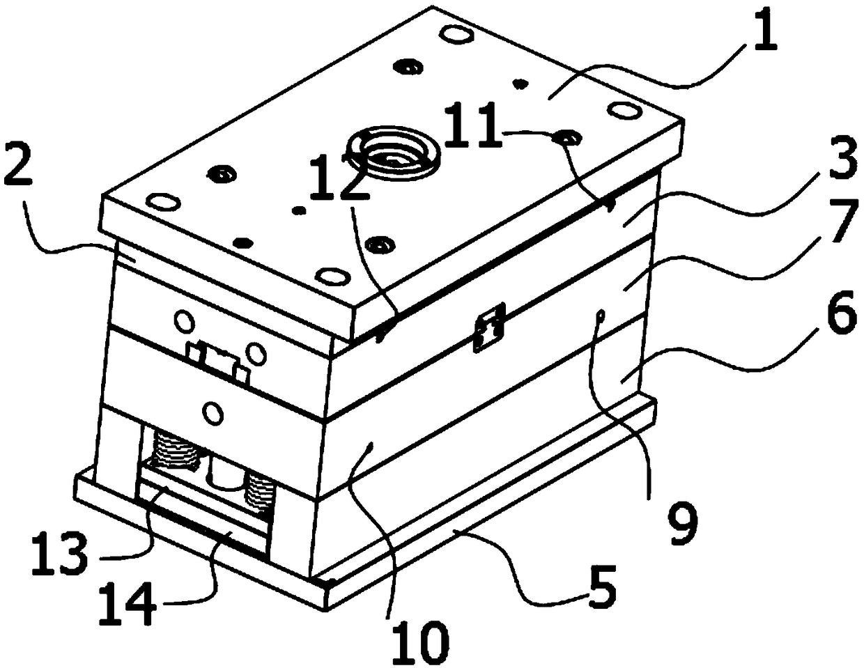
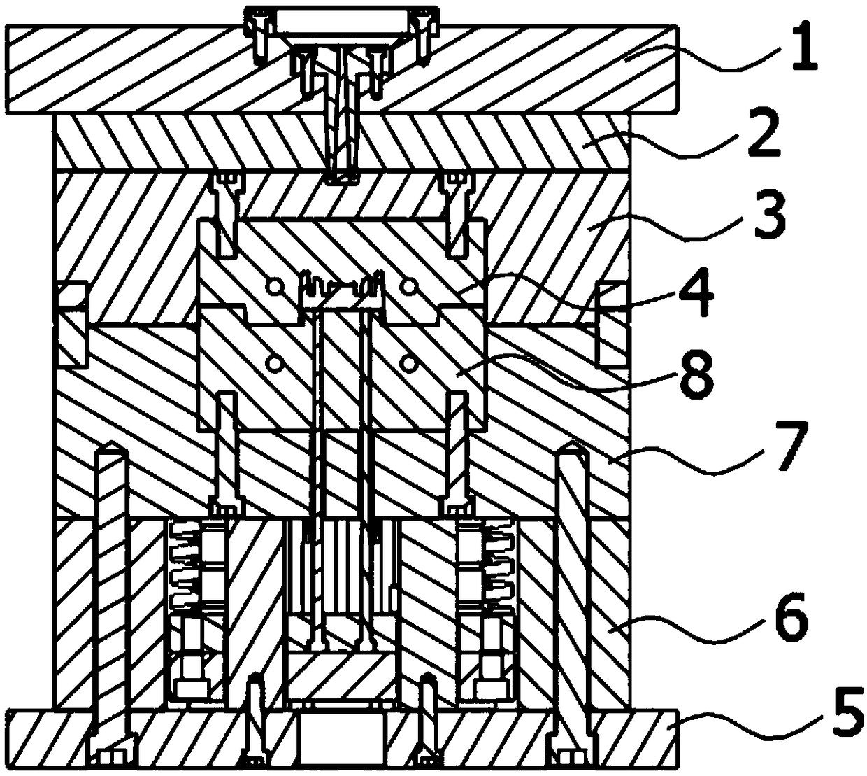
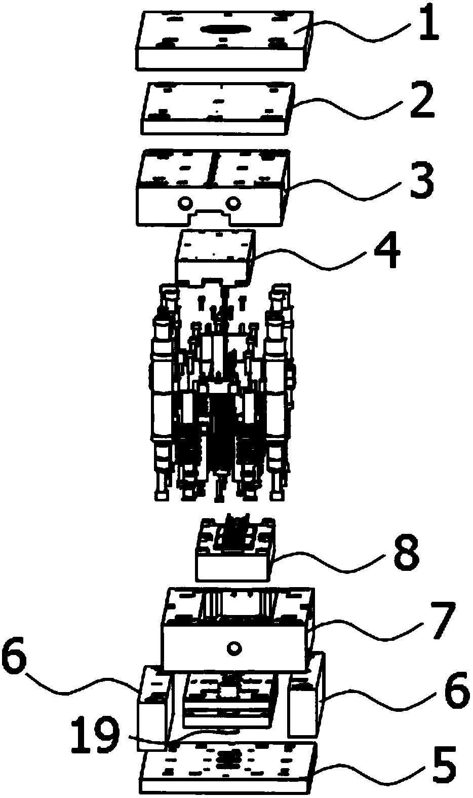
[0052] Embodiment: a kind of glass light guide plate injection mold and light guide plate injection molding process, such as Figure 1-Figure 7 As shown, it includes a male mold base and a female mold base used in conjunction with each other; the female mold base includes a panel 1, a nozzle plate 2, a female template 3 and a female mold core 4, and the panel, the nozzle plate and the female mold base The three templates can be separated and connected, and the female mold core is fixed on the inner side of the female template; the male mold seat includes a base plate 5, a die foot 6, a male template 7 and a male mold core 8, and the base plate, mold feet and male template The three are fixedly connected, the male mold core is fixed on the inner side of the male template; the cavity of the light guide plate is formed between the female mold core and the male mold core; the female mold base has a glue inlet; the male mold core The seat has an ejection structure for ejecting the ...


PUM

PropertyMeasurementUnit
heightaaaaaaaaaa
diameteraaaaaaaaaa
diameteraaaaaaaaaa

Abstract

The invention discloses a glass light guide plate injection mold and a light guide plate injection molding process. The glass light guide plate injection mold comprises a male mold holder and a femalemold holder which are used in cooperation. The female mold holder comprises a panel, a stripper plate, a female mold plate and a female mold core. The male mold holder comprises a bottom plate, moldlegs, a male mold plate and a male mold core. A light guide plate cavity is formed between the female mold core and the male mold core. The male mold holder is internally provided with a male mold cooling water runner. The female mold holder is internally provided with a female mold cooling water runner. A positioning structure used for relative sliding of the male mold holder and the female moldholder is included. The positioning structure further comprises positioning sleeves fixedly connected with the periphery of the male mold plate and positioning rods fixedly connected with the female mold plate, and further comprises positioning convex blocks located on the side wall of the male mold plate and positioning grooves located in the side wall of the female mold plate. According to the mold, positioning stability of the male mold holder and the female mold holder can be improved through matched sleeving connection of the positioning sleeves and the positioning rods and matched clamping connection of the positioning convex blocks and the positioning grooves.

Description

technical field [0001] The invention belongs to the technical field of moulds, in particular to an injection mold for a glass light guide plate. Background technique [0002] With the continuous improvement of people's living standards, plastic products have become an indispensable synthetic material in modern life. Plastic has the advantages of light weight, stable chemical properties, excellent electrical insulation properties, good noise reduction and shock absorption, high specific strength, and wide distribution of mechanical strength. Injection molding technology is to add granular or powdery polymer raw materials into the polymer barrel, plasticize under heating or mechanical shearing, and finally enter the mold under the push of a plunger or screw, and cool and solidify to form a mold cavity. Consistent polymer articles. Injection molding technology is one of the main processing methods of plastic products and can produce and manufacture complex molded products at ...

Claims


Application Information

Patent Timeline
Patent Type & Authority Applications(China)
IPC IPC(8): B29C45/26B29C45/00B29C45/76B29L11/00
CPCB29C45/0025B29C45/2602B29C45/76B29L2011/00
Inventor 钟健
Owner 昆山弘正电子科技有限公司
Learn More