Microstrip patch antenna, array and array design method working in the millimeter wave band

A technology of microstrip patch antenna and millimeter wave band, which is applied in the direction of separately energized antenna array, antenna array, and antenna array manufacturing device, etc. It can solve the problems of complex antenna array design, poor cross-polarization characteristics, and dependence on air layers, etc. , to achieve good cross-polarization characteristics, large gain, and overcome the effect of poor cross-polarization characteristics

Active Publication Date: 2021-05-04
苏州速感智能科技有限公司
View PDF8 Cites 0 Cited by
  • Summary
  • Abstract
  • Description
  • Claims
  • Application Information

AI Technical Summary

Problems solved by technology

[0006] In order to solve the problems of small bandwidth, low gain, poor cross-polarization characteristics, excessive dependence on the air layer, and complex antenna array design in existing antennas; the invention discloses a microstrip patch antenna working in the millimeter wave band, Arrays and Array Design Methods

Method used


Image

  • Microstrip patch antenna, array and array design method working in the millimeter wave band
  • Microstrip patch antenna, array and array design method working in the millimeter wave band
  • Microstrip patch antenna, array and array design method working in the millimeter wave band

Examples


Embodiment Construction

[0045] In order to make the object, technical solution and advantages of the present invention clearer, the present invention will be further described in detail below in conjunction with the accompanying drawings.

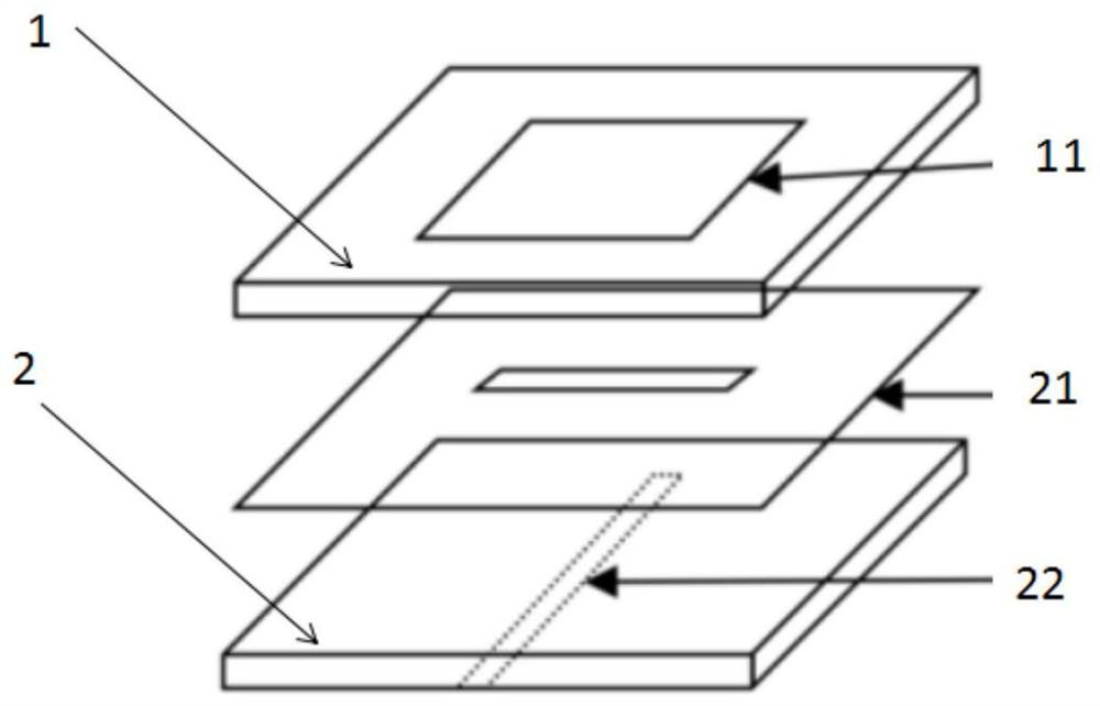
[0046] The embodiment of the present invention discloses a microstrip patch antenna working in the millimeter wave band, such as figure 1 As shown, the microstrip patch antenna is connected by pressing the lower surface of the first dielectric substrate 1 and the upper surface of the second dielectric substrate 2, and the upper surface of the first dielectric patch 1 is arranged with In the radiation patch 11, a feeding network with slots is arranged in the second dielectric substrate 2.

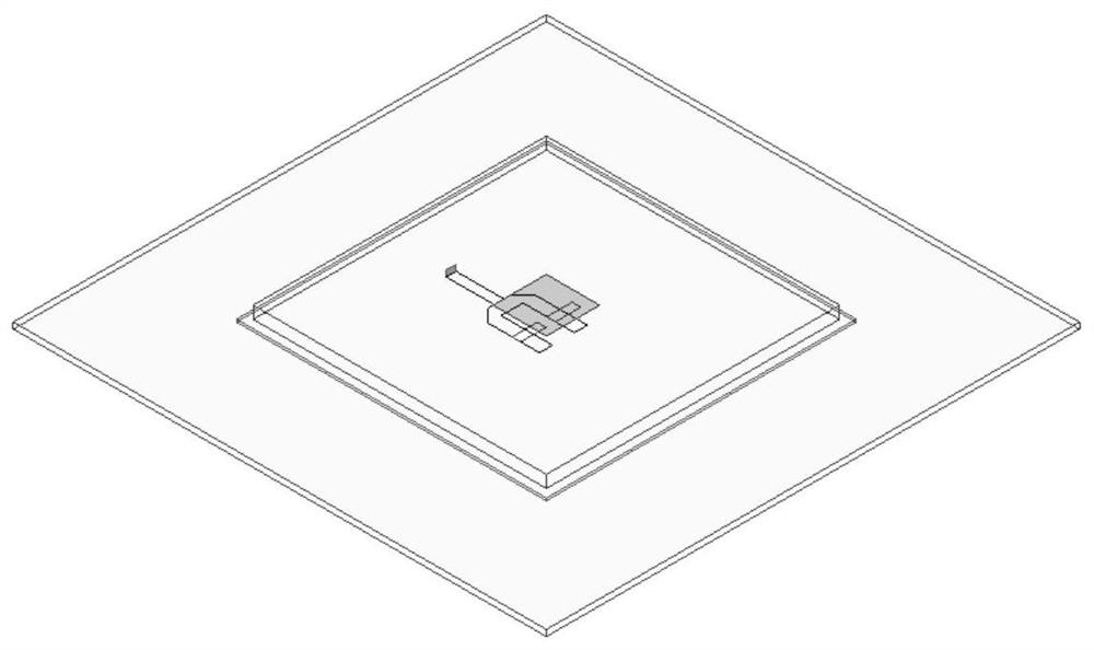
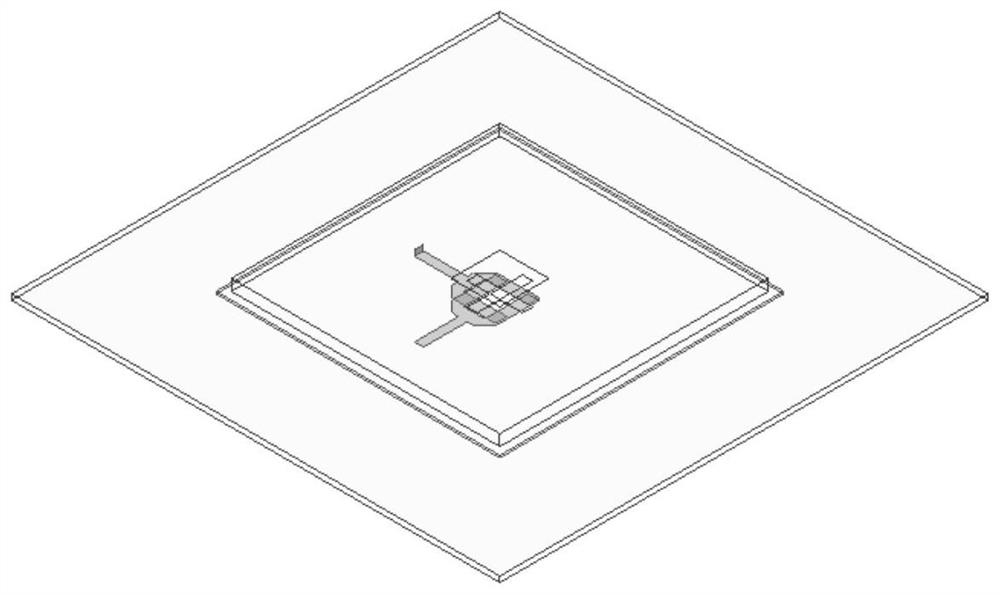
[0047] Specifically, there are two types of microstrip patch antennas, one is an antenna under a single-polarization condition, and the other is an antenna under a dual-polarization condition. Please refer to figure 2 , which shows a three-dimensional schematic diagram of a d...


PUM

PropertyMeasurementUnit
impedanceaaaaaaaaaa

Abstract

The invention provides a microstrip patch antenna working in the millimeter wave band, an array and an array design method. The microstrip patch antenna working in the millimeter wave band is connected by the lower surface of the first dielectric substrate and the upper surface of the second dielectric substrate by means of pressing, and the upper surface of the first dielectric patch is arranged with radiation A patch, a feeding network with slits is arranged on the second medium substrate. The microstrip patch antenna of the present invention works in the millimeter wave band by selecting a medium with a dielectric constant similar to that of air to make a substrate, and is prepared by a pressing process, thereby avoiding the problems of difficult processing caused by introducing an air layer and unstable performance. , and has the characteristics of high bandwidth, high cross-polarization suppression, and high sidelobe suppression. The antenna array has significant advantages such as simple structure, large bandwidth, large gain, and good cross-polarization characteristics. In the design method of the antenna array, the effective current distribution can be realized only by designing the impedance distribution of the feeder, and the design is simpler and more flexible.

Description

technical field [0001] The invention belongs to the field of communication, and is particularly suitable for the field of 5G communication; the invention specifically relates to a microstrip patch antenna, an array and an array design method working in the millimeter wave band. Background technique [0002] In the coupled-feed antenna, the antenna and the feeder are not directly connected, but the feeder and the antenna are designed on different dielectric layers, and the feed is carried out through electromagnetic coupling; the bandwidth can be significantly increased when the structure complexity is slightly increased, but It is difficult to achieve more than 8%, thus limiting the bandwidth and data rate of the system. In order to increase the bandwidth, the dielectric material of the slot coupling structure is often replaced by an air layer; since the bandwidth of the microstrip antenna is inversely proportional to the dielectric constant, and the loss of the air layer is...

Claims


Application Information

Patent Timeline
Patent Type & Authority Patents(China)
IPC IPC(8): H01Q1/38H01Q1/50H01Q21/00H01Q21/06
CPCH01Q1/38H01Q1/50H01Q21/0006H01Q21/0093H01Q21/061
Inventor 卢杰吴九冬
Owner 苏州速感智能科技有限公司
Why Eureka
Try Eureka