
Construction device for river cofferdam diversion and application method thereof

A technology for construction devices and rivers, applied in water conservancy engineering, marine engineering, infrastructure engineering and other directions, can solve the problems of low construction efficiency, river cofferdam ditching, complicated operation steps, etc., so as to reduce the operation intensity and facilitate the excavation work. , the effect of ensuring safety

Inactive Publication Date: 2018-12-25
浙江省正邦水电建设有限公司
View PDF7 Cites 0 Cited by
  • Summary
  • Abstract
  • Description
  • Claims
  • Application Information

AI Technical Summary

Problems solved by technology

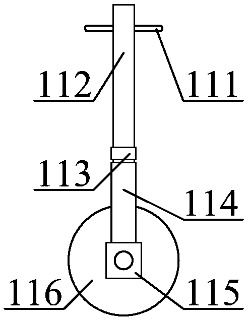
[0010] In order to solve the above technical problems, the present invention provides a river cofferdam diversion construction device and its use method, to solve the existing river cofferdam diversion construction device can not ditch the river cofferdam, does not have The function of cleaning weeds inside the river, the operation steps are cumbersome, it is impossible to measure and determine the depth of the river, and it is very easy to cause the risk of collapse during construction. Due to the heavy workload, it is inconvenient to disassemble and move the device, resulting in low construction efficiency and inconvenient storage of river garbage. Construction device for river cofferdam diversion, including conventional bearings, main concave connecting seat, auxiliary concave connecting seat, machine base, fixing nut, adjusting screw, rotating handle, linear slide rail, U-shaped slider, fixed sleeve, Height-adjustable rapid displacement wheel structure, river depth auxiliary measuring telescopic rod structure, river cofferdam bank along diversion excavation diversion wheel structure, river garbage collection auxiliary salvage pocket structure and garbage dewatering temporary storage box structure, the main interior A conventional bearing is inlaid in the middle position of the inner lower left side of the concave connecting seat; a conventional bearing is inlaid in the middle position of the inner lower right side of the auxiliary concave connecting seat; The inner right end recess of the seat, and the other end bolt nut is installed in the inner left end recess of the auxiliary concave connecting seat; the fixed nut is embedded in the inner middle position of the machine base; the longitudinal thread of the adjustment screw is connected to the fixed The inner middle position of the nut; the upper end of the adjustment screw is welded at the middle position of the horizontal lower part of the rotating handle; the horizontal bolt of the linear slide rail is installed at the middle position of the lower left side of the machine base; the U-shaped slider is slidingly clamped on The middle position of the lower part of the outer wall of the linear slide rail; the fixed sleeve is longitudinally welded at the middle position of the front surface of the U-shaped slider; the vertical upper ends of the height-adjustable quick-displacement wheel structures are respectively installed in the main concave joint through conventional bearings The lower part of the seat and the auxiliary concave connection seat; the auxiliary depth measurement telescopic rod structure of the river is installed in the middle position of the right end of the auxiliary concave connection seat; The lower end of the screw rod; the river garbage collection auxiliary salvage pocket structure is installed on the inner lower side of the fixed casing; the garbage dewatering temporary storage box structure is installed on the inner right middle position of the machine base; the height adjustable Adjusting the fast displacement wheel structure includes a rotation auxiliary rod, a height rotation screw, a fastening nut, an internal thread pipe, a wheel seat and a moving wheel, and the rotation auxiliary rod is horizontally threaded on the inner upper side of the height rotation screw; the height The longitudinal lower end of the rotating screw runs through the inner middle position of the fastening nut and is threadedly connected to the inner upper side of the inner threaded pipe; the longitudinal lower end of the inner threaded pipe is welded at the upper middle position of the wheel seat; the moving wheel shaft is connected to the wheel seat rear middle position of

Method used

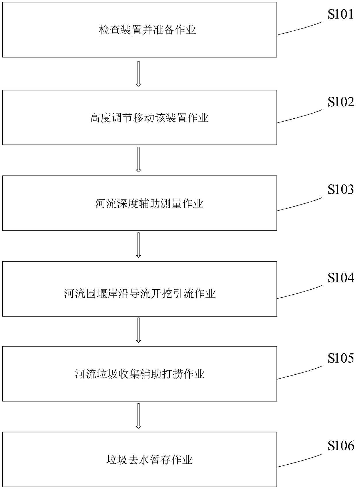

Image

  • Construction device for river cofferdam diversion and application method thereof
  • Construction device for river cofferdam diversion and application method thereof
  • Construction device for river cofferdam diversion and application method thereof

Examples


Embodiment Construction

[0059] The present invention will be further described below in conjunction with accompanying drawing:

[0060] In the picture:

[0061] as attached figure 2 to attach Figure 7 shown

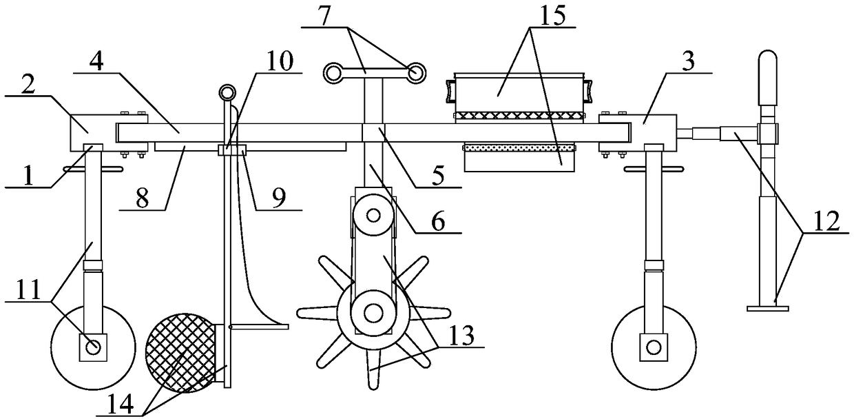
[0062] A construction device for river cofferdam flow diversion, including a conventional bearing 1, a main concave connecting seat 2, an auxiliary concave connecting seat 3, a machine base 4, a fixing nut 5, an adjusting screw 6, a rotating handle 7, and a linear slide rail 8 , U-shaped slider 9, fixed casing 10, height-adjustable quick-displacement wheel structure 11, river depth auxiliary measurement telescopic rod structure 12, river cofferdam bank along the diversion excavation diversion wheel structure 13, river garbage collection auxiliary salvage pocket Structure 14 and garbage dewatering temporary storage box structure 15, the middle position of the inner lower left side of the main concave type connecting seat 2 is inlaid with a conventional bearing 1; the middle position of the i...


PUM


Abstract

The invention provides a construction device for river cofferdam diversion. The construction device for the river cofferdam diversion comprises a conventional bearing, a main internal concave type connecting seat, an auxiliary internal concave type connecting seat, a machine base, a fixing nut, an adjusting screw, a rotating handle, a liner sliding rail, a U-shaped sliding block, a fixing sleeve,a height adjustable quick displacement wheel structure, a river depth auxiliary measuring telescopic rod structure, a river cofferdam shore edge diversion excavation drainage wheel structure, a rivergarbage collecting auxiliary salvaging bag structure and a garbage water removal temporary storage box structure. By arranging a rotating auxiliary rod, a high-rotating screw, a fastening nut, an internal thread pipe, a wheel seat and a moving wheel, the moving operation of the device can be carried out, and meanwhile, the height adjusting operation can be carried out; and the use requirement is met, and the construction device for the river cofferdam diversion is used for solving the problem that an original device is low in construction efficiency due to large workload and inconvenient disassembly and movement.

Description

technical field [0001] The invention belongs to the technical field of road engineering, and in particular relates to a construction device for river cofferdam flow diversion and an application method thereof. Background technique [0002] When tunnel engineering and pipeline engineering are under the river and cross-river bridge construction, it is necessary to carry out cofferdam diversion measures for the river, so as to provide a good working environment for the construction of the lower tunnel and pipeline, or the construction of the upper bridge, so that the tunnel and pipeline The water content of the upper soil layer is reduced, reducing the infiltration of the river, or providing a better working environment for the bridge pile foundation construction through orderly drainage, and reducing the impact of disorderly drainage of the river on the construction. [0003] The commonly used cofferdam diversion methods are mainly four methods: cutting off the flow, laying wa...

Claims


Application Information

Patent Timeline
Patent Type & Authority Applications(China)
IPC IPC(8): E02D19/04E02B3/00E02B15/10
CPCE02B3/00E02B15/10E02D19/04
Inventor 贺志贞
Owner 浙江省正邦水电建设有限公司
Learn More