
Die cutting method for keeping finished product edge of packaging paper box being flush with paper gripper edge

An edge and paper technology, which is applied in the field of die-cutting where the edge of the finished packaging carton is flush with the edge of the paper mouth, can solve the problems of reducing waste paper edges, reducing connection points, and paper edge waste, saving paper costs, The effect of reducing connection points and reducing workload

Active Publication Date: 2018-12-25
杭州淘艺数据技术有限公司
View PDF4 Cites 4 Cited by
  • Summary
  • Abstract
  • Description
  • Claims
  • Application Information

AI Technical Summary

Problems solved by technology

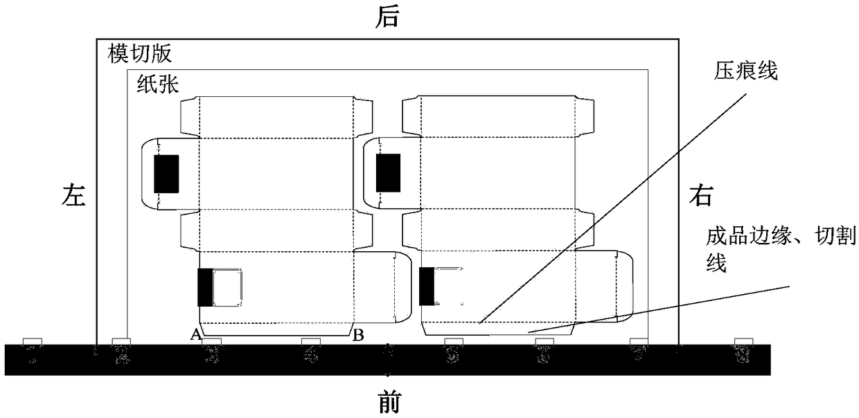
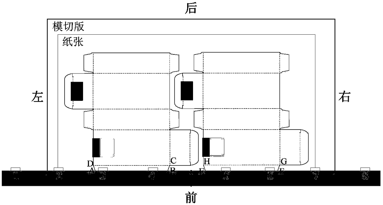
[0004] The technical problem to be solved by the present invention is to propose a die-cutting method in which the edge of the finished product of the packaging carton is flush with the edge of the paper gripper, so that the gripper of the die-cutting machine does not collide with the die-cutting plate steel knife or steel wire. , directly hold the edge of the finished product for die-cutting, which not only solves the problem of paper edge waste and reduces the workload of removing waste paper edges, but also the die-cut paper is not easy to be broken and affect the production efficiency during the transfer process, and it can also reduce the connection point, good for aesthetics and cleanup

Method used


Image

  • Die cutting method for keeping finished product edge of packaging paper box being flush with paper gripper edge
  • Die cutting method for keeping finished product edge of packaging paper box being flush with paper gripper edge
  • Die cutting method for keeping finished product edge of packaging paper box being flush with paper gripper edge

Examples


Embodiment Construction

[0026] The present invention will be further described in detail below with reference to the drawings and embodiments.

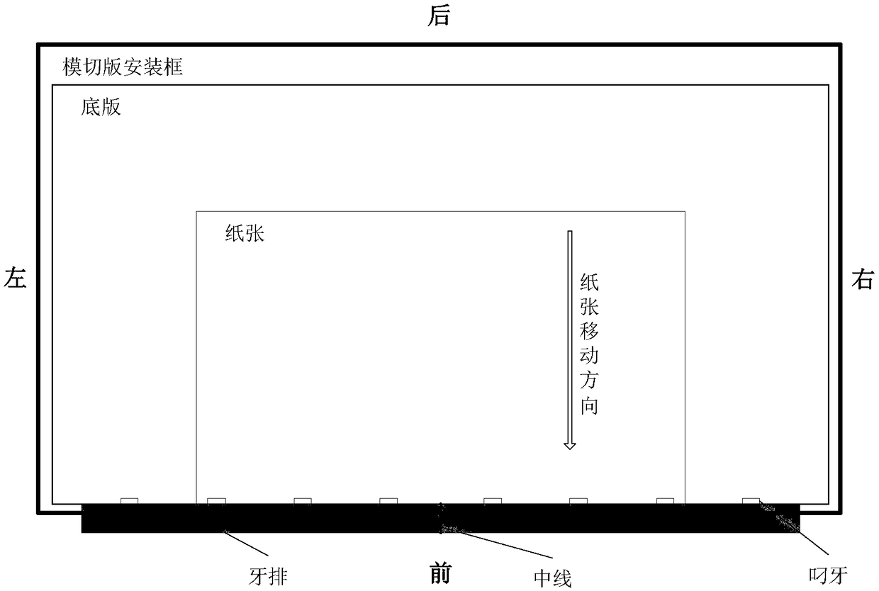
[0027] In the packaging and printing industry, the die-cutting and forming processing of sheet paper mainly adopts the horizontal flat-bed die-cutting machine with automatic paper feeding for die-cutting and creasing processing. On a typical horizontal flat die-cutting machine, the relative positions of the die-cutting master, die-cutting plate mounting frame, and the biter row are fixed. The position of the paper relative to the die-cutting master during die-cutting can pass the front gauge A small amount of movement in the front and rear direction is performed, and a large amount of movement in the left and right direction is performed by the side guide. When the front rule is at the reference position, the relative positions between the die-cut master, die-cut plate mounting frame, the biter row and the paper are as follows: figure 1 As shown, the gripping e...


PUM


Abstract

The invention discloses a die cutting method for keeping the finished product edge of a packaging paper box being flush with a paper gripper edge. The die cutting method comprises the steps that 1, the position, printed on paper, of an image is adjusted so that the finished product edge on the paper can be flush with the gripper edge; 2, a steel knife is not placed at the finished product edge, and a die cutting plate is produced with the distance difference formed between the inner edge, in the front-back direction, of a die cutting plate mounting frame and the front edge of a bottom plate asthe distance between the edge of a finished product and the plate edge; 3, the mounting position, in the left-right direction and on a die cutting machine, of the die cutting plate is adjusted, so that gripper teeth do not touch the steel knife and a steel wire of a transverse cutting plate; and 4, transverse cutting is started, and a front lay and side lays of the die cutting machine are adjusted according to the finished product requirement. By means of the die cutting method, the problem that paper edges are wasted is solved, and the work amount for clearing away the waste paper edges is reduced; in addition, the problem that the paper obtained after die cutting is likely to be broken in the delivery process to affect production efficiency is avoided; connecting points can be reduced;and the attractive appearance and waste removal can be achieved conveniently.

Description

Technical field [0001] The invention relates to the field of post-press processing in the packaging and printing industry, in particular to a die-cutting method in which the edge of the finished packaging carton is flush with the edge of the paper gripper. Background technique [0002] For paper-based packaging printed matter, if the printing quantity is not particularly large, a single sheet of paper is generally used for printing and post-press processing. In the printing and die-cutting processes, it is necessary to grip the gripping edge of the paper, which plays the role of transferring the paper and determining the position of the paper. However, when printing, the gripping part of the paper edge cannot touch the blanket and the ink adheres to it due to the presence of the gripper of the printer; during die cutting, the die-cutting plate corresponding to the gripping part of the paper cannot have a steel knife or Steel wire, otherwise the gripper of the die-cutting machine...

Claims


Application Information

Patent Timeline
Patent Type & Authority Applications(China)
IPC IPC(8): B31B50/20
CPCB31B50/20
Inventor 余节约
Owner 杭州淘艺数据技术有限公司
Learn More