
Lathe cooling device for gear machining

A technology for cooling devices and lathes, applied in metal processing equipment, metal processing machinery parts, manufacturing tools, etc., can solve the problems of precision machine tools that cannot take away all the heat, cooling effect deviation, and affecting processing accuracy, etc., so as to be suitable for promotion and use, Simple structure and reasonable design effect

Inactive Publication Date: 2018-12-25
合肥银泉铸造有限责任公司
View PDF8 Cites 4 Cited by
  • Summary
  • Abstract
  • Description
  • Claims
  • Application Information

AI Technical Summary

Problems solved by technology

[0003] In the gear processing lathe, due to the high-speed operation of the machine and the friction between the workpiece and the tool, a large amount of heat will be generated. In order to avoid the deformation of the workpiece caused by the increase in heat and affect the machining accuracy, the workpiece needs to be cooled in time. The existing technology, cooling
While cutting the workpiece, the friction between the workpiece and the tool generates a lot of heat. In order to avoid the deformation of the workpiece caused by the increase in heat and affect the machining accuracy, it is necessary to cool the workpiece in time, especially on precision machine tools. Good cooling is more important. However, in the prior art, the coolant is pressurized and cooled by an ordinary cooling pump. Due to insufficient pressure, the heat generated by the precision machine tool during the machining process cannot be taken away completely, and the cooling effect is deviated.

Method used


Image

  • Lathe cooling device for gear machining
  • Lathe cooling device for gear machining

Examples


Embodiment Construction

[0017] The technical solutions in the embodiments of the present invention will be clearly and completely described below in conjunction with the accompanying drawings in the embodiments of the present invention. Obviously, the described embodiments are only some of the embodiments of the present invention, not all of them. Based on The embodiments of the present invention and all other embodiments obtained by persons of ordinary skill in the art without making creative efforts belong to the protection scope of the present invention.

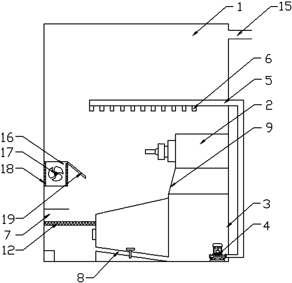
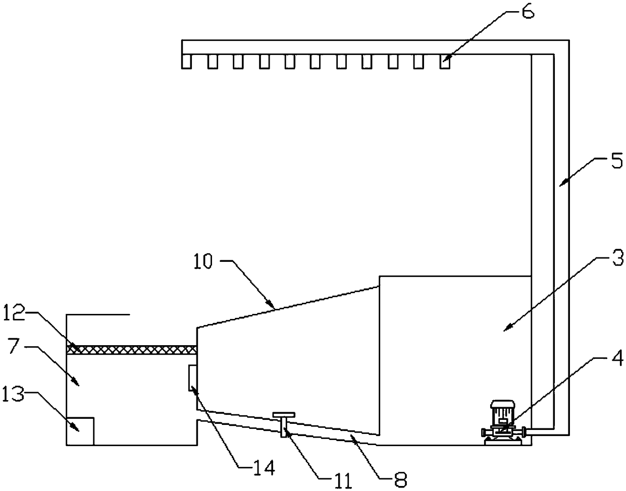
[0018] see Figure 1-2 , the present invention provides a technical solution: a lathe cooling device for gear processing, including a device main body 1, a cutting device main body 2 is installed inside the device main body 1, a cooling box 3 is provided at the bottom of the cutting device main body 2, and the inside of the cooling box 3 The bottom end is equipped with a liquid pump 4, one end of the liquid pump 4 is connected to a liquid suctio...


PUM


Abstract

The invention discloses a lathe cooling device for gear machining. A cooling tank is arranged, so that the storage function of cooling liquid is realized, further the cooling liquid in the cooling tank is pumped out to a nozzle to be sprayed by an infusion pump, and the cooling for a main cutting device body after working is realized. Residual liquid after cooling passes through a first sloping plate and a second sloping plate and then reaches a recovery room, and residual metal debris is filtered down by a filtration and adsorption plate. The remaining residual liquid reaches the bottom end of the recovery room, and the heat is dissipated through a heat exchange plate; and after a temperature sensor senses that the temperature reaches a certain value, a control valve is opened, and the recycling of the cooling liquid is realized. The cooled residual heat is absorbed and dissipated out by an exhaust fan, impurities are prevented from being emitted to the outside world through a filterscreen, the liquid sprayed out from the nozzle is prevented from entering an air outlet pipe through a liquid baffle plate, and further the working and the service life of the exhaust fan cannot be affected. The lathe cooling device has the advantages of simple structure and reasonable design, is more humanized, and is suitable for promotion and use.

Description

technical field [0001] The invention relates to the field of gear processing, in particular to a lathe cooling device for gear processing. Background technique [0002] A lathe is a machine tool that mainly uses a turning tool to turn a rotating workpiece. Drills, reamers, reamers, taps, dies and knurling tools can also be used for corresponding processing on the lathe. A gear is a mechanical element with gears on the rim that continuously mesh to transmit motion and power. The application of gears in transmission has appeared very early. At the end of the 19th century, the principle of generative gear cutting method and special machine tools and cutting tools using this principle appeared one after another. With the development of production, the stability of gear operation was paid more attention. [0003] In the gear processing lathe, due to the high-speed operation of the machine and the friction between the workpiece and the tool, a large amount of heat will be gener...

Claims


Application Information

Patent Timeline
Patent Type & Authority Applications(China)
IPC IPC(8): B23Q11/10B23Q11/12
CPCB23Q11/10B23Q11/12
Inventor 朱晓林
Owner 合肥银泉铸造有限责任公司
Learn More