Powder coating processing device

A processing device, powder coating technology, applied in the direction of solid separation, sieves, grids, etc., can solve the problems of poor uniformity, inconvenient operation, and poor crushing quality of coating, so as to improve the screening efficiency and screening quality, and facilitate the The effect of processing and improving the crushing quality

Inactive Publication Date: 2018-12-25
周兆平
View PDF1 Cites 1 Cited by
  • Summary
  • Abstract
  • Description
  • Claims
  • Application Information

AI Technical Summary

Problems solved by technology

[0003] The purpose of the present invention is to provide a reasonable structure design, convenient operation, high crushing efficiency, Powder coating processing equipment with good uniformity of coating pulverization and less waste of raw materials

Method used


Image

  • Powder coating processing device
  • Powder coating processing device

Examples


Embodiment 1

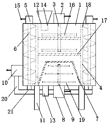
[0017] as attached figure 1 Shown: a powder coating processing device, including a silo 1, a motor 2, a drive shaft 3, a partition 4, a motor 2 5, an auger 6, a screen cylinder 7, a motor 3 8, a rotating shaft 9 and a blower 10, It is characterized in that the silo is set on the bracket 11, the feed silo 12 is set on the top of the silo 1, and the discharge pipe 13 is set on the bottom of the silo 1, and the motor one 2 is set on the silo 1 top, and a power cord 15 is set on the motor one 2, the transmission shaft 3 is set in the silo 1, one end of the transmission shaft 3 is connected with the motor one 2, and a crushing rod 16 is arranged on the transmission shaft 3 , the partition 4 is arranged in the silo 1, a sieve plate 17 is arranged between the partition 4 and the partition 4, the motor two 5 is arranged on the top of the bin 1, and the motor two 5 is set There is a power cord 15, the auger 6 is arranged between the inner wall of the silo 1 and the partition 4, and th...

Embodiment 2

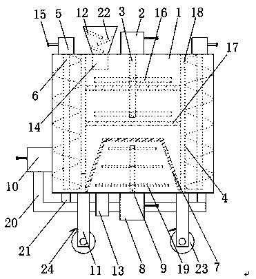
[0024] as attached figure 2 Shown: a powder coating processing device, including a silo 1, a motor 2, a drive shaft 3, a partition 4, a motor 2 5, an auger 6, a screen cylinder 7, a motor 3 8, a rotating shaft 9 and a blower 10, It is characterized in that the silo is set on the bracket 11, the feed silo 12 is set on the top of the silo 1, and the discharge pipe 13 is set on the bottom of the silo 1, and the motor one 2 is set on the silo 1 top, and a power cord 15 is set on the motor one 2, the transmission shaft 3 is set in the silo 1, one end of the transmission shaft 3 is connected with the motor one 2, and a crushing rod 16 is arranged on the transmission shaft 3 , the partition 4 is arranged in the silo 1, a sieve plate 17 is arranged between the partition 4 and the partition 4, the motor two 5 is arranged on the top of the bin 1, and the motor two 5 is set There is a power cord 15, the auger 6 is arranged between the inner wall of the silo 1 and the partition 4, and t...


PUM


Abstract

The invention discloses a powder coating processing device which comprises a material bin, a first motor, a transmission shaft, a clapboard, a second motor, a packing auger, a screening barrel, a third motor, a rotary shaft and a blower. The powder coating processing device is characterized in that the material bin is arranged on a support frame, the first motor is arranged on the top of the material bin, the transmission shaft is arranged in the material bin, the clapboard is arranged in the material bin, the second motor is arranged on the top of the material bin, the packing auger is arranged between the inner wall of the material bin and the clapboard, the screening barrel is arranged at the bottom in the material bin, and the third motor is arranged at the bottom of the material bin.According to the powder coating processing device, a material falling pipe connected with a feeding bin is arranged on the top in the material bin, on the one hand, the material falling pipe can prevent powder coating from being blown into the feeding bin by a gas flow carried by the packing auger, thus the condition of returning of the powder coating is avoided, on the other hand, the powder coating in the feeding bin can fully fall on a screening board to be ground, processing of the powder coating is convenient, working efficiency is improved, and waste of the powder coating is reduced.

Description

technical field [0001] The invention relates to the technical field of paint processing, in particular to a powder paint processing device. Background technique [0002] Environmentally friendly powder coatings are an important type of coatings, and their fineness directly affects the quality and performance of powder coatings. Most of the existing methods are to pulverize the raw materials of powder coatings, but the existing pulverization devices generally have work efficiency. The problem of low crushing efficiency and poor crushing quality. For example, the patent application number 201710243720.4 discloses environmentally friendly epoxy powder coating processing equipment, which solves the problem of low crushing efficiency, but it has the disadvantages of inconvenient operation, low crushing quality, and paint crushing. The problem of poor uniformity. Contents of the invention [0003] The purpose of the present invention is to provide a reasonable structure design,...

Claims


Application Information

Patent Timeline
Patent Type & Authority Applications(China)
IPC IPC(8): B02C13/18B02C23/14B07B1/46B02C13/284B02C13/286B02C13/288
CPCB02C13/18B02C13/284B02C13/286B02C13/288B02C23/14B02C2013/28654B07B1/4609B07B2201/04
Inventor 周兆平张强汪永生
Owner 周兆平
Why Eureka
Try Eureka