
Spinning rotor for an open-end spinning machine having a friction-enhancing lining made of an elastomeric material, and open-end spinning machine

A technology of increasing friction and free end, applied in the direction of free end spinning machine, continuous winding spinning machine, spinning machine, etc., can solve the problems of large energy consumption and increased bending work in the rotor support area, and achieve favorable Effects of vibration damping performance, reduced slippage, and reduced energy consumption

Inactive Publication Date: 2018-12-21
RIETER INGOLSTADT GMBH
View PDF11 Cites 0 Cited by
  • Summary
  • Abstract
  • Description
  • Claims
  • Application Information

AI Technical Summary

Problems solved by technology

This leads to an increased bending work in the lining of the support disk, which results in considerable energy dissipation in the rotor bearing area

Method used


Image

  • Spinning rotor for an open-end spinning machine having a friction-enhancing lining made of an elastomeric material, and open-end spinning machine
  • Spinning rotor for an open-end spinning machine having a friction-enhancing lining made of an elastomeric material, and open-end spinning machine
  • Spinning rotor for an open-end spinning machine having a friction-enhancing lining made of an elastomeric material, and open-end spinning machine

Examples


Embodiment Construction

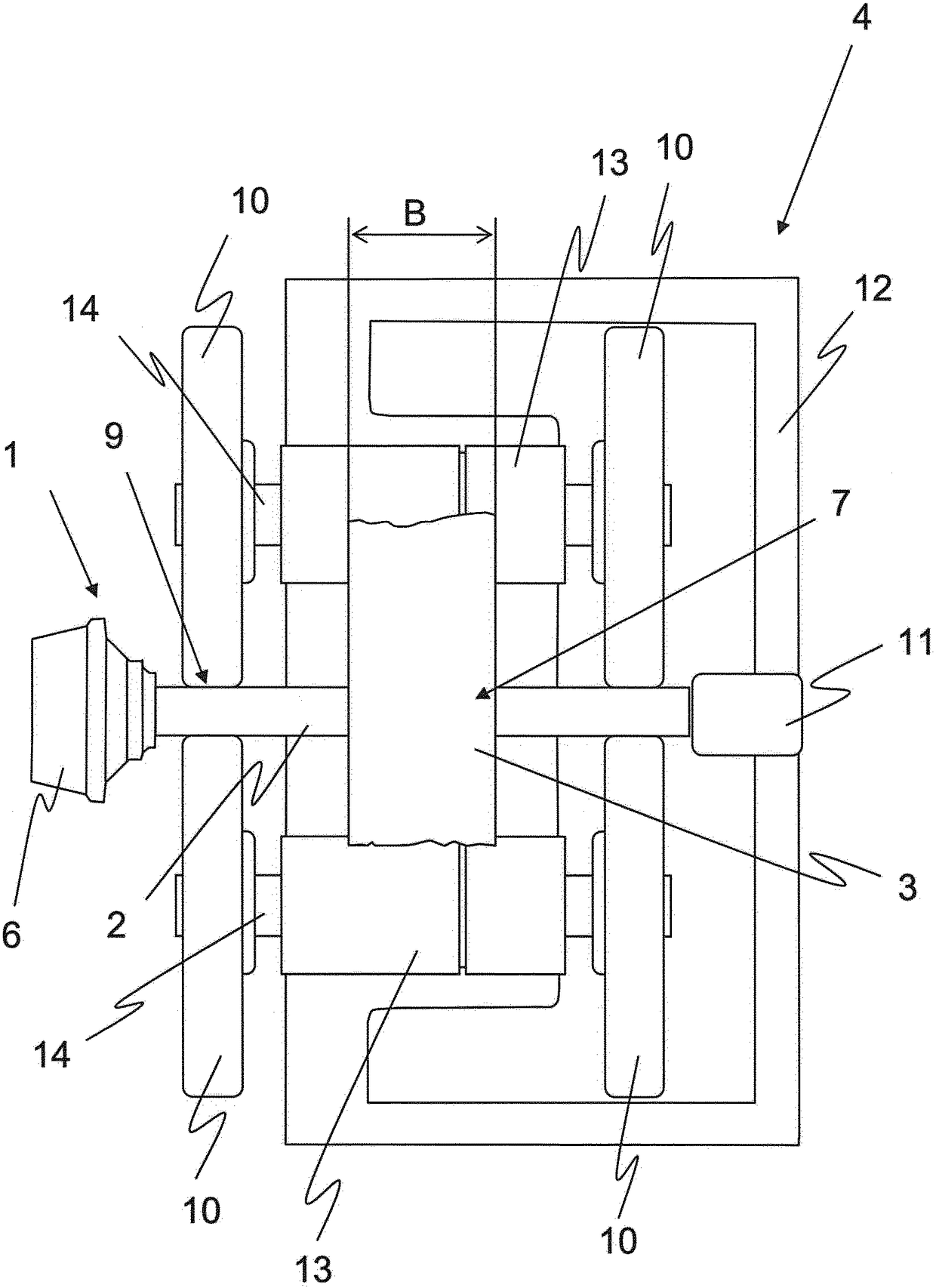
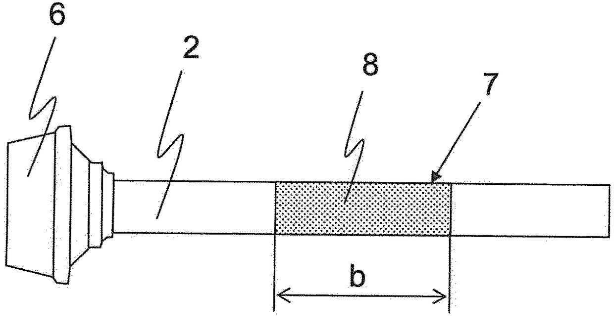
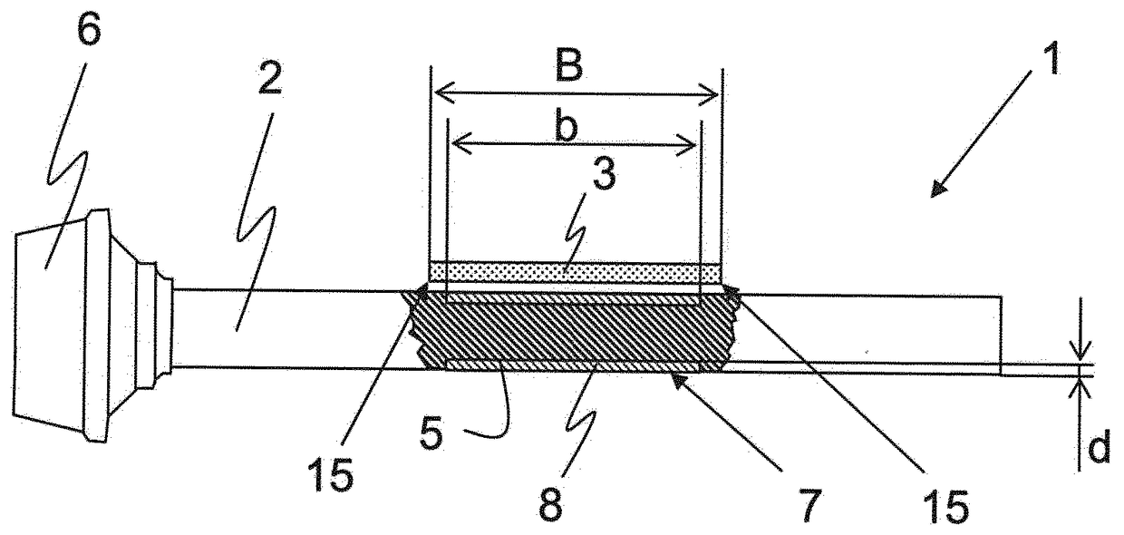
[0021] figure 1 An open-end spinning device 4 with a spinning rotor 1 and a belt 3 for driving the spinning rotor 1 is shown in a schematic plan view. The spinning rotor 1 generally consists of a rotor shaft 2 and a rotor cup 6 , which can be detachable or fixedly connected to the rotor shaft 2 . The spinning device 4 comprises a conventional bearing arrangement for the spinning rotor 1 , which in the present example is designed in the form of a support disc bearing. In this case, for the radial support of the spinning rotor, two support disk bearings 13 are accommodated in a bearing seat 12 in which in turn a shaft 14 is supported in each case. In this case, each of the two shafts 14 carries a support disk 10 at its two ends. The two shafts 14 with the support disks 10 are now arranged in such a way that between each two support disks 10 a wedge-shaped gap 9 is formed in which the spinning rotor 1 can be accommodated with its rotor shaft 2 . Between the two thus formed pai...


PUM

PropertyMeasurementUnit
elastic modulusaaaaaaaaaa

Abstract

A spinning rotor (1) for an open-end spinning machine (4) has a rotor shaft (2), via which the spinning rotor (1) is able to be driven by means of a belt (3), in particular a tangential belt. The rotor shaft (2) has a contact region (7) for the belt (3). In the contact region (7), the rotor shaft (2) has a friction-enhancing lining (8) made of an elastomeric material. In an open-end spinning machine (4) having a spinning rotor (1) and having a belt (3), in particular a tangential belt, for driving the spinning rotor (1), the spinning rotor (1) is provided with a friction-enhancing lining (8) made of an elastomeric material.

Description

technical field [0001] The invention relates to a spinning rotor for an open-end spinning device having a rotor shaft via which the spinning rotor can be driven by means of a belt, in particular a tangential belt. The rotor shaft has a contact area for the belt. Background technique [0002] In the case of spinning rotors of open-end spinning machines, the spinning rotor has long been generally driven by means of a tangential belt placed on the shaft of the spinning rotor. The spinning rotor is usually supported on a support disc. The belt is generally pressed against the rotor shaft by additional drive rollers to reduce slippage between the belt and the rotor shaft. In this case it is also possible to vary the pressure force of the pressure rollers in order to achieve, for example, a faster start-up of the spinning rotor or to adapt to different spinning materials or the like. An open-end spinning device is shown, for example, in DE 10107254 A1 with pressure rollers whic...

Claims


Application Information

Patent Timeline
Patent Type & Authority Applications(China)
IPC IPC(8): D01H4/10D01H4/12
CPCD01H4/10D01H4/12D01H1/241
Inventor D·格赖斯
Owner RIETER INGOLSTADT GMBH
Learn More