A horizontal diode device
A technology of lateral diodes and devices, which is applied in the direction of semiconductor devices, semiconductor/solid-state device manufacturing, electrical components, etc., can solve the problems of poor reverse blocking ability and low forward conduction current density, and achieve good forward voltage drop, The effect of improving the voltage blocking ability and improving the rectification efficiency
- Summary
- Abstract
- Description
- Claims
- Application Information
AI Technical Summary
Problems solved by technology
Method used
Image
Examples
Embodiment 1
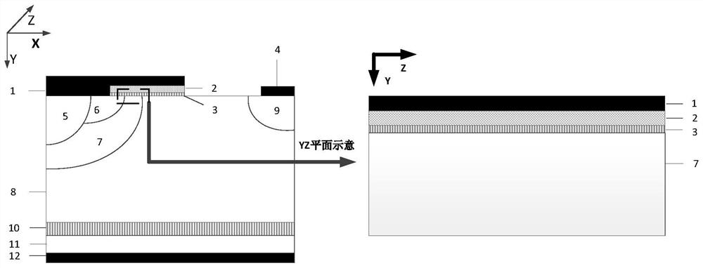
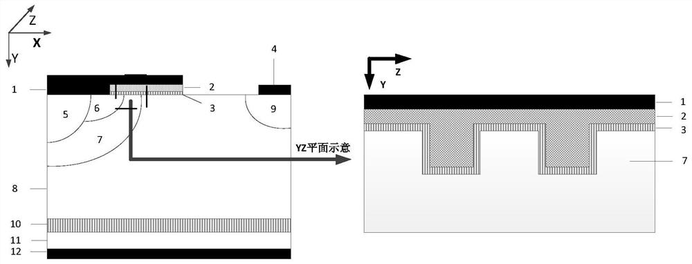
[0067] This embodiment takes the structure of a 600V lateral diode device as an example, as figure 2 As shown, the cellular structure of the lateral diode device in this embodiment includes a substrate electrode 12, an N-type silicon carbide substrate 11, a dielectric layer 10, and an N-silicon carbide drift region 8 arranged sequentially from bottom to top, and N- A P-type silicon carbide base region 7 is set on one side of the top layer of the silicon carbide drift region 8, and an N+ silicon carbide drain region 9 is set on the other side; the upper surface of the N+ silicon carbide drain region 9 has a cathode metal 4; the top layer of the P-type silicon carbide base region 7 is arranged side by side Set P+ silicon carbide contact region 5 and N+ silicon carbide source region 6, N+ silicon carbide source region 6 is located on the side close to N+ silicon carbide drain region 9 and its depth does not exceed the depth of P+ silicon carbide contact region 5; N+ silicon carbi...
Embodiment 2
[0070] This embodiment makes a certain degree of modification to embodiment 1, and its structure is roughly the same as that of embodiment 1, the difference is that there is also an anode metal 1 inside the groove structure, that is, the depth of the lower surface of the anode metal 1 is deeper than that of the groove at the top of the structure, such as Figure 7 shown. This improvement can reduce the gate resistance, increase the charging speed of the gate charge, and further optimize the rectification performance of the device, so that the gate control capability of the device is further improved.
Embodiment 3
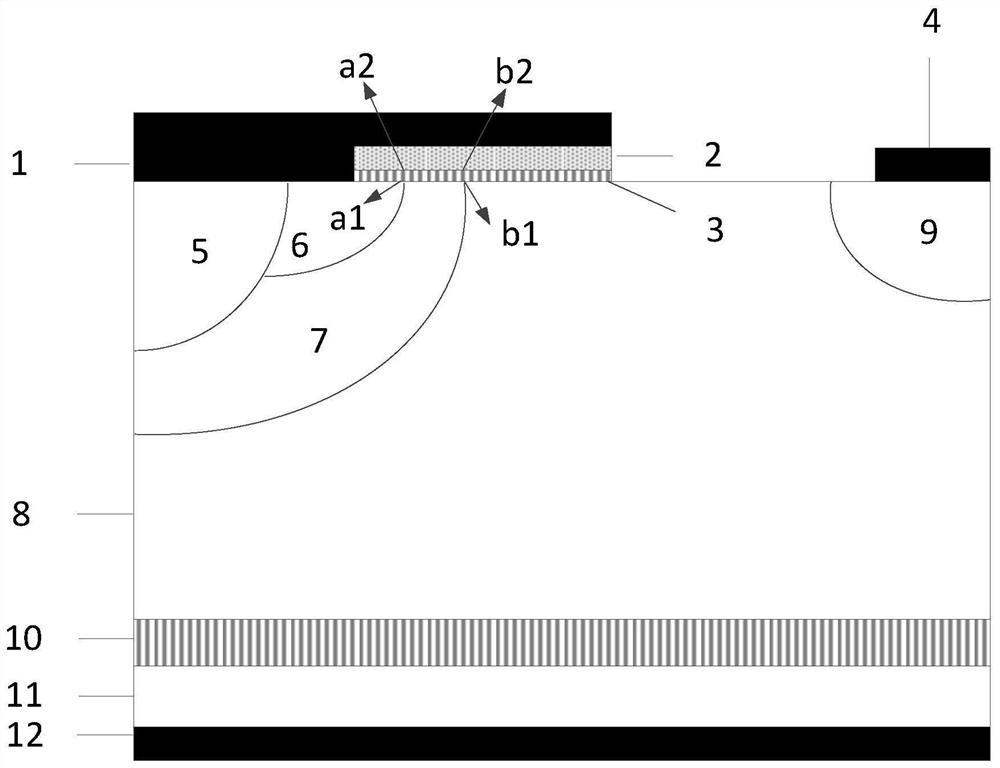
[0072] This embodiment makes some modifications to Embodiment 1 and Embodiment 2, and its structure is roughly the same as that of Embodiment 2. The difference is that in this embodiment, the gate structure extends toward the N+ silicon carbide drain region 9, And one end of the polysilicon 2 close to the N+ silicon carbide drain region 9 is in contact with the upper surface of the N- silicon carbide drift region 8 to form a Si / SiC heterojunction with rectification characteristics, and the junction width is about 0.1 μm to 0.3 μm, such as Figure 8 shown. The lateral diode device in this embodiment has a three-dimensional super-barrier structure and a Si / SiC heterojunction, and the heterojunction significantly increases the forward conduction current level of the diode in this embodiment.
PUM
| Property | Measurement | Unit |
|---|---|---|
| thickness | aaaaa | aaaaa |
| width | aaaaa | aaaaa |
| width | aaaaa | aaaaa |
Abstract
Description
Claims
Application Information
 - R&D Engineer
- R&D Manager
- IP Professional
- Industry Leading Data Capabilities
- Powerful AI technology
- Patent DNA Extraction
Browse by: Latest US Patents, China's latest patents, Technical Efficacy Thesaurus, Application Domain, Technology Topic, Popular Technical Reports.
© 2024 PatSnap. All rights reserved.Legal|Privacy policy|Modern Slavery Act Transparency Statement|Sitemap|About US| Contact US: help@patsnap.com


