
Object-image doubly telecentric adjustable imaging lens

An imaging lens and adjustable technology, applied in the field of optical systems, can solve problems such as low pixel resolution, and achieve the effect of high resolution and high telecentricity

Pending Publication Date: 2018-12-21
JIAXING ZHONGRUN OPTICAL TECH
View PDF0 Cites 4 Cited by
  • Summary
  • Abstract
  • Description
  • Claims
  • Application Information

AI Technical Summary

Problems solved by technology

[0003] The present invention aims at the defect that the existing telecentric lens cannot meet the high level of telecentricity at the object side and the image side at the same time, and the pixel resolution is low, because the introduction of the coaxial light source needs to add a prism module to the optical system and Insufficient, an adjustable imaging lens with double telecentricity of object and image is proposed, which has high telecentricity and 8M high resolution; at the same time, the prism module of this lens can be removed, realizing a set of optical system, coaxial light source \ non- Advantages of two working modes of coaxial light source

Method used


Image

  • Object-image doubly telecentric adjustable imaging lens
  • Object-image doubly telecentric adjustable imaging lens
  • Object-image doubly telecentric adjustable imaging lens

Examples


Embodiment 1

[0024] Such as figure 1 As shown, this embodiment includes sequentially from the object plane side to the image plane side along the light incident direction: a first lens group G1 with positive power, a detachable folding prism P, a diaphragm S, and a second lens group with negative power. Lens group G2, image surface IMG.

[0025] The first lens group G1 includes: a first lens L1 with positive refractive power, a second lens L2 with negative refractive power, a third cemented lens L3 with positive refractive power whose cemented surface faces the object side, and a third cemented lens L3 with negative optical power. The fourth cemented lens L4 with the focal cemented surface facing the object side, and the fifth lens L5 with positive refractive power.

[0026] The second lens group G2 includes: a sixth cemented lens L6 with a negative power cemented surface facing the object side, a seventh lens L7 with a negative power, an eighth lens L8 with a negative power, and a The n...

Embodiment 2

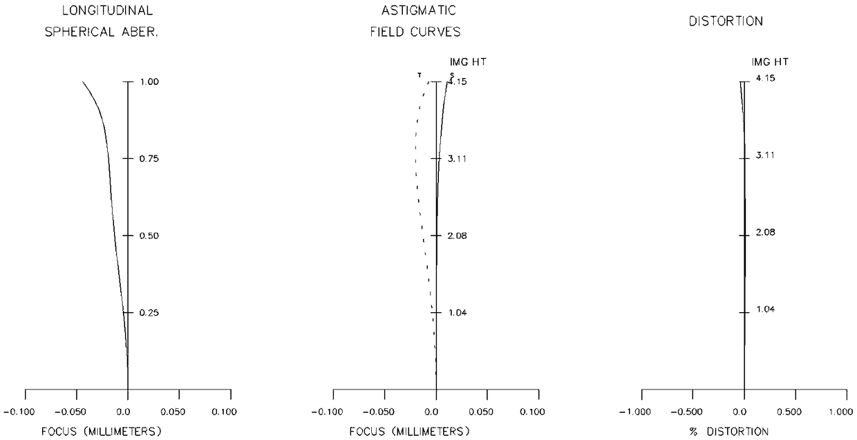
[0040] Such as image 3Shown is a schematic diagram of the structure of this embodiment. Compared with Embodiment 1, the folding prism in Embodiment 1 is removed in this embodiment, so that the light source of the optical system is changed from a coaxial light source to a non-coaxial light source. After the prism is removed, all lens parameters of the entire optical system remain unchanged. Adjusting the position of each lens in the second lens group with respect to the optical axis direction can satisfy refocusing imaging, while basically not changing the resolution and telecentricity of the lens. At the same time, the overall length of the lens in this embodiment is shortened, which can be applied to the field of small industrial lenses.

[0041] Specifically, the lens of this embodiment has an effective focal length of 250mm and an object-image distance of 244mm.

[0042] The lens structure parameters of the present embodiment are specifically as follows:

[0043]

[...


PUM


Abstract

The invention discloses an object-image doubly telecentric adjustable imaging lens, which sequentially comprises a first lens group with positive optical power, a removable turn-back prism, a diaphragm and a second lens group with negative optical power from an object side to an image side, wherein the first lens group comprises at least one fourth cemented lens which has negative optical power and of which the cemented surface is toward an object; and the second lens group comprises at least one ninth cemented lens which has positive optical power and of which the cemented surface is toward the object. The object-image doubly telecentric adjustable imaging lens has high telecentricity and high resolution of 8M; and meanwhile, a prism module of the lens can be removed, thereby achieving the advantage that one set of optical system has two working modes of a coaxial light source and a non-coaxial light source.

Description

technical field [0001] The invention relates to a technology in the field of optical systems, in particular to an adjustable imaging lens capable of removing prisms, dual-purpose object-side and image-side double-telecentric. Background technique [0002] The telecentric lens is mainly designed to correct the parallax of traditional industrial lenses. It can keep the magnification of the obtained image within a certain range of object distance. It is generally divided into two types: object-space telecentricity and image-space telecentricity. The feature of object-space telecentric optical path is that the converging center of object-space principal rays parallel to the optical axis is located at infinity in object-space, which can eliminate reading errors caused by inaccurate focusing in object-space. The feature of the telecentric optical path in the image space is that the convergence center of the chief light rays parallel to the optical axis is located at infinity in th...

Claims


Application Information

Patent Timeline
Patent Type & Authority Applications(China)
IPC IPC(8): G02B13/22
CPCG02B13/22
Inventor 诸益炜尚洁阳盛亚茗
Owner JIAXING ZHONGRUN OPTICAL TECH
Learn More