Feeding device for calcining refractory bricks

A refractory brick and calcination technology, applied in the field of refractory bricks, can solve the problems of poor safety, large workload and low efficiency.

Inactive Publication Date: 2018-12-21
明光瑞尔非金属材料有限公司
View PDF7 Cites 2 Cited by
  • Summary
  • Abstract
  • Description
  • Claims
  • Application Information

AI Technical Summary

Problems solved by technology

[0002] At present, in the process of refractory brick processing, the raw materials of refractory bricks need to go through processes such as crushing, mixing, and calcination. In these processes, the raw materials of refractory bricks need to be added to the silo and then transported to the corresponding equipment. It can improve the processing efficiency of refractory brick raw materials. In the traditional calcination, feeding is carried out manually with simple fixtures. This method not only has a large workload and low efficiency, but also has high labor intensity and safety for operators. poor problem

Method used


Image

  • Feeding device for calcining refractory bricks
  • Feeding device for calcining refractory bricks
  • Feeding device for calcining refractory bricks

Examples


Embodiment Construction

[0021] The following will clearly and completely describe the technical solutions in the embodiments of the present invention with reference to the accompanying drawings in the embodiments of the present invention. Obviously, the described embodiments are only some, not all, embodiments of the present invention. All other embodiments obtained by persons of ordinary skill in the art based on the embodiments of the present invention belong to the protection scope of the present invention.

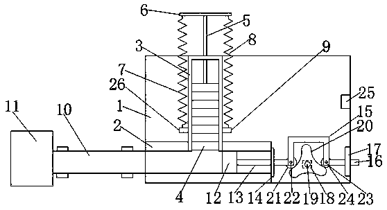
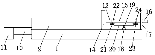
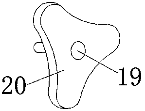
[0022] According to an embodiment of the present invention, a feeding device for calcining refractory bricks is provided.

[0023] Such as Figure 1-3 As shown, a feeding device for refractory brick calcination according to an embodiment of the present invention includes a workbench 1, a chute-2 is provided on the upper end of the workbench 1, and one side of the chute-2 is located at The workbench 1 is provided with a chute 2 3, a number of refractory bricks 4 are arranged in the chute 2 3,...


PUM


Abstract

The invention discloses a feeding device for calcining refractory bricks. The feeding device comprises a workbench, wherein a chute I is arranged in the upper end of the workbench; a chute II is arranged in one side of the chute I and is located in the workbench; a plurality of refractory bricks are arranged in the chute II; an ejector rod is arranged at the upper end of the refractory brick; oneend, away from the refractory brick, of the ejector rod penetrates through one side of the chute II and extends to the outer side of the chute II; a supporting rod is arranged at one end of the ejector rod and is located on the outer side of the chute II; a spring I is arranged on one side of the supporting rod; a spring II is arranged on the other side of the supporting rod; a connecting block Iis arranged on one end, far away from the supporting rod, of the spring I and is located on the lower end of one side of the chute II; a connecting block II is arranged on one end, far away from the supporting rod, of the spring II and is located on the lower end of the other side of the chute II; a conveying belt is arranged on one side of the chute I and is located on the outer side of the workbench; a calcining chamber is arranged on one side, away from the workbench, of the conveying belt; and a sliding block matched with the chute I is arranged on the other side of the chute I.

Description

technical field [0001] The invention relates to the field of refractory bricks, in particular to a feeding device for firing refractory bricks. Background technique [0002] At present, in the process of refractory brick processing, the raw materials of refractory bricks need to go through processes such as crushing, mixing, and calcination. In these processes, the raw materials of refractory bricks need to be added to the silo and then transported to the corresponding equipment. It can improve the processing efficiency of refractory brick raw materials. In the traditional calcination, feeding is carried out manually with simple fixtures. This method not only has a large workload and low efficiency, but also has high labor intensity and safety for operators. Poor question. [0003] Aiming at the problems in the related technologies, no effective solution has been proposed yet. Contents of the invention [0004] Aiming at the problems in the related art, the present i...

Claims


Application Information

Patent Timeline
IPC IPC(8): F27D3/00
Inventor 徐瑞图
Owner 明光瑞尔非金属材料有限公司
Why Eureka
Try Eureka