Sponge-type double-layer tube drainage system

A drainage system and double-layer pipe technology, which is applied in the waterway system, sewer system, and sewage discharge, can solve problems such as insufficient infiltration, reduced rainfall utilization, and loose foundations, so as to facilitate infiltration, prevent soil clogging, and facilitate cleaning Effect

Pending Publication Date: 2018-12-21
XIAMEN UNIV OF TECH
View PDF1 Cites 0 Cited by
  • Summary
  • Abstract
  • Description
  • Claims
  • Application Information

AI Technical Summary

Problems solved by technology

[0003] The existing drainage system of the sponge city is mainly divided into two types, one is to rely on the infiltration and absorption of green land itself, and the other is to rely on the rainwater pipe network to discharge rainwater into the urban drainage system, but in the rainy season or heavy rain, due to the ground runoff And the instantaneous flood peak flow is large, only the green space itself absorbs water and the rainwater pipe network cannot quickly solve the drainage pressure, which will easily cause waterlogging in the sponge city, and the rainwater will be directly drained instead of stored, reducing the use of rainfall
Therefore also someone proposes to transform the rainwater pipeline into a seepage system, such as the sponge type rainwater infiltration collection and drainage system proposed by CN206360052U, but this scheme still exists in the rainy season or when the rainstorm, the surface runoff and the instantaneous flood peak flow are large, the infiltration is not timely enough, and large The drainage with high flow rate and high flow rate will impact the foundation of the pipeline, causing the foundation to loosen and causing safety hazards

Method used


Image

  • Sponge-type double-layer tube drainage system
  • Sponge-type double-layer tube drainage system

Examples


Embodiment Construction

[0018] To further illustrate the various embodiments, the present invention is provided with accompanying drawings. These drawings are a part of the disclosure of the present invention, which are mainly used to illustrate the embodiments, and can be combined with related descriptions in the specification to explain the operating principles of the embodiments. With reference to these contents, those skilled in the art should understand other possible implementations and advantages of the present invention. Components in the figures are not drawn to scale, and similar component symbols are generally used to denote similar components.

[0019] The present invention will be further described in conjunction with the accompanying drawings and specific embodiments.

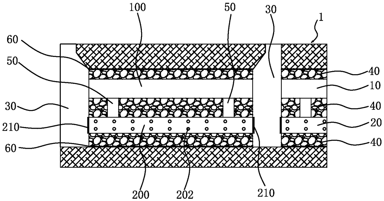
[0020] Such as figure 1 As shown, the present invention provides a sponge-type double-layer pipe drainage system, including a drainage pipeline 10, a seepage pipeline 20 and several standpipes 30, and the drainage pipe...


PUM


Abstract

The invention relates to a sponge-type double-layer tube drainage system. The sponge-type double-layer tube drainage system comprises a drainage pipeline, a water permeation pipeline and multiple vertical tubes. The drainage pipeline and the water permeation pipeline are arranged under the ground in the horizontal direction, the water permeation pipeline is located under the drainage pipeline, thegap between the drainage pipeline and the water permeation pipeline and the bottom of the water permeation pipeline are bedded with gravel beds, the vertical tubes are vertically arranged under the ground at specific intervals, the drainage pipeline is composed of multiple segments of drainage pipes, the water permeation pipeline is composed of multiple segments of water permeation pipes, the corresponding drainage pipe and the corresponding water permeation pipe communicated with every two vertical tubes are arranged between the two adjacent vertical tubes, multiple water permeation holes are formed in the peripheral walls of the water permeation pipes, the water permeation pipes are communicated with the drainage pipes through multiple connecting tubes, seal end covers are installed atthe two ends of each water permeation pipe, and therefore rainwater can be intercepted to the maximum degree and be prevented from impacting the gravel beds to the maximum degree.

Description

technical field [0001] The invention relates to the field of urban drainage systems, in particular to a sponge-type double-layer pipe drainage system. Background technique [0002] With the rapid development of cities and more and more large-scale construction, while improving the living environment of human beings, it also brings safety problems represented by urban drainage and waterlogging. In order to overcome this safety problem, the concept of "sponge city" was proposed, which uses measures such as infiltration, stagnation, storage, purification, utilization, and drainage to absorb and utilize most of the rainfall on the spot. [0003] The existing drainage system of the sponge city is mainly divided into two types, one is to rely on the infiltration and absorption of green land itself, and the other is to rely on the rainwater pipe network to discharge rainwater into the urban drainage system, but in the rainy season or heavy rain, due to the ground runoff And the in...

Claims


Application Information

Patent Timeline
IPC IPC(8): E03F1/00E03F3/02E03F3/04
CPCE03F1/001E03F3/02E03F3/043
Inventor 代智能阳艾利傅海燕龙绛雪
Owner XIAMEN UNIV OF TECH
Why Eureka
Try Eureka