Cloth boundary recognition method for sewing machine and sensor and identification device thereof

A boundary recognition and sewing machine technology, applied in sewing equipment, sewing machine components, cloth feeding mechanisms, etc., can solve the problems of large data processing volume, slow response speed, inconvenient installation, etc., to improve recognition accuracy, improve stability, avoid The effect of false detection

Pending Publication Date: 2018-12-21
福恩达机器人(昆山)有限公司
View PDF0 Cites 1 Cited by
  • Summary
  • Abstract
  • Description
  • Claims
  • Application Information

AI Technical Summary

Problems solved by technology

[0004] At present, there are two or three types of sensors used in the sewing industry on the market: infrared diffuse emission type and reflective optical fiber sensor, but they are all single-dot type sensors, which have large diameters of detection dots, low precision, and inconvenient installation. Edge recognition sensors are generally placed evenly within a fixed length range. When the selvedge is within this length range, the position of the selvedge is determined by judging whether the reflective optical fiber sensor is blocked, and the recognition of the fabric boundary is realized.
The scheme of diffuse reflection infrared sensor and optical fiber sensor is adopted. Since the diameter of the reflective optical fiber head is generally about 3mm, the accuracy error of detecting the edge of the cloth is at least greater than 3mm. Some occasions that require high precision cannot be used, and the reflective optical fiber The sensor has an influence on the color of the fabric and the height of the fabric from the fiber optic head, and it is difficult to debug
[0005] The other is our most commonly used industrial camera. The above-mentioned industrial camera has good precision and installation, but it has high cost, large data processing capacity and slow response speed. Real-time alignment requires a large computer platform, which eventually leads to cost Too high is not acceptable for the sewing industry

Method used


Image

  • Cloth boundary recognition method for sewing machine and sensor and identification device thereof
  • Cloth boundary recognition method for sewing machine and sensor and identification device thereof
  • Cloth boundary recognition method for sewing machine and sensor and identification device thereof

Examples


Embodiment Construction

[0026] The embodiments of the present invention will be described in detail below with the aid of the drawings.

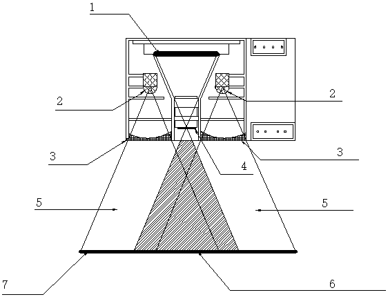
[0027] A cloth boundary recognition sensor of a sewing machine includes a lens group 4 and a linear CCD photosensitive chip 1 located on one side of the lens group 4, and is characterized in that at least two groups are arranged around the lens group 4 and directed to the other side of the lens group. The linear light source composed of 2 and the concave lens 3 is provided with a reflector 7 that reflects the linear light source back to the lens group 4 on the other side of the lens group.

[0028] A cloth boundary recognition device for a sewing machine, which is characterized by comprising a lens group 4 and a linear CCD photosensitive chip 1 on one side of the lens group 4. At least two groups are arranged around the lens group 4 and directed to the other side of the lens group. The linear light source composed of 2 and concave lens 3 is provided on the other side of...


PUM


Abstract

The invention relates to a cloth boundary recognition method for a sewing machine and a sensor and an identification device thereof, and belongs to the technical field of intelligent automatic sewingrobot control. A red light LDE light source is converted into a linear light source through a multiple layers of lens, the linear light source is reflected by a reflector to a lens group to be concentrated to form a point-distance linear beam, the point-distance linear beam is irradiated on a linear CCD sensor to form analog voltage output of a dot array, and the cloth boundary recognition sensoris constituted. The analog voltage of the dot array outputted by the cloth boundary recognition sensor is directly sent to an AD port of a MCU for calculation processing, and a digital quantity is transmitted outward through a communication circuit to constitute the cloth boundary identification device of the sewing machine. The cloth boundary recognition sensor adopts a linear CCD photosensitivechip, and the recognition precision is greatly improved; the MCU directly receives an analog voltage value, and the digital quantity is transmitted outward through the communication circuit after thecalculation processing, thereby avoiding interference on an analog signal transmitting over a long distance, and improving the stability of the cloth boundary identification sensor.

Description

Technical field [0001] The invention discloses a cloth boundary recognition method, sensor and recognition device of a sewing machine, belonging to the technical field of intelligent automatic sewing robot control. Background technique [0002] Nowadays, sewing automation is the development trend of the sewing industry, which can greatly improve labor productivity and reduce manufacturing costs. For sewing automation, the sensor is like its eyes. With it, it can accurately identify the presence and color of the fabric. , Position, etc., so as to realize the functions of grasping, moving and sewing the fabric. [0003] The cloth edge recognition sensor (abbreviated as cloth edge recognition sensor) is one of them. It is used to identify the position of the cloth edge. The robot arm adjusts the cloth to the correct position by comparing the current position of the cloth with the correct position, and realizes the control of the cloth. Correction. [0004] At present, there are two or...

Claims


Application Information

Patent Timeline
Patent Type & Authority Applications(China)
IPC IPC(8): D05B35/10
CPCD05B35/102
Inventor 史颜亮
Owner 福恩达机器人(昆山)有限公司
Why Eureka
Try Eureka