
Horizontal circulation type magnetic levitation conveyor belt

A conveyor belt and circular technology, which is applied in the field of horizontal circular magnetic levitation conveyor belt, can solve the problems of easy wear of the moving guide rail and supporting guide rail, inability to automatically unload goods, and large loss of power components, so as to avoid derailment, enrich unloading, and avoid wear and tear Effect

Pending Publication Date: 2018-12-21
NANJING FORESTRY UNIV
View PDF6 Cites 4 Cited by
  • Summary
  • Abstract
  • Description
  • Claims
  • Application Information

AI Technical Summary

Problems solved by technology

The magnetic levitation conveyor belt uses the magnetic levitation technology to realize the non-contact transmission between the power element and the moving part, which effectively solves the problems of easy wear between the moving guide rail and the supporting guide rail of the traditional conveyor belt, high maintenance cost and large loss of the power element. At present, most of the common maglev conveyor belts are U-shaped groove structures. For the transportation of bulk goods such as coal, this structure has higher requirements on the transportation speed and stability of the conveyor belt. In addition, the existing maglev conveyor belts often cannot automatically unload goods.

Method used


Image

  • Horizontal circulation type magnetic levitation conveyor belt
  • Horizontal circulation type magnetic levitation conveyor belt
  • Horizontal circulation type magnetic levitation conveyor belt

Examples


Embodiment Construction

[0032] Embodiments of the present invention will be further described in detail below in conjunction with the accompanying drawings.

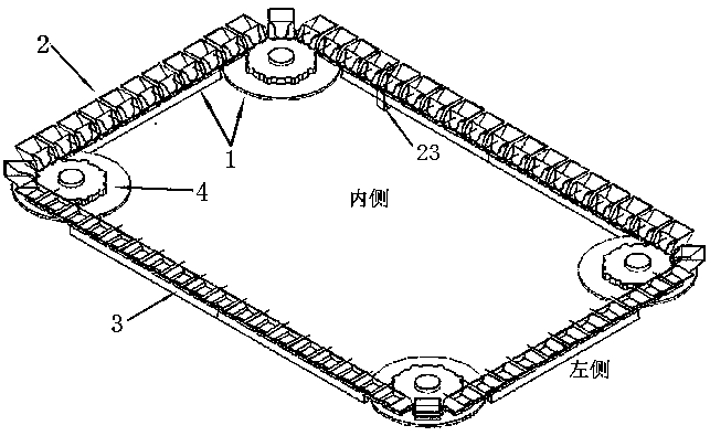
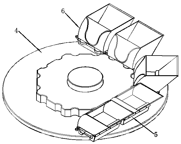
[0033] A horizontal circulating suspension conveyor belt, including a track 1 and a conveyor belt 2, the track 1 is composed of a horizontally placed straight section guide rail 3 and a turning guide wheel 4, the turning guide wheel 4 connects each straight section guide rail 3 end to end, and the conveyor belt 2 is set on the track 1, the conveyor belt 2 is composed of several moving units, the moving unit includes a moving seat 5 and a box body 6, wherein, the bottom of the moving seat 5 is equipped with a secondary power element, and the rear side of the moving seat 5 is provided with a first hollow shaft 7, and the box The bottom of the rear side of the body 6 is provided with a second hollow shaft 8, through the cooperation of the first hollow shaft 7 and the second hollow shaft 8, the box body 6 is hinged on the kinematic seat 5, and the f...


PUM


Abstract

The invention discloses a horizontal circulation type magnetic levitation conveyor belt. A track is composed of horizontally arranged straight section guide rails and steering guide wheels for connecting the guide rails end to end. The conveyor belt is arranged on the track and composed of moving bases and box bodies arranged on the moving bases. The bottom of each moving base is provided with a secondary power component. Primary power components are mounted at first grooves of the guide rails. First hook grooves and second hook grooves of the moving bases are provided with first electromagnets. Second grooves of the guide rails are provided with second electromagnets. After power is applied, the moving bases are suspended on the guide rails through attraction cooperation of the first electromagnets at the first hook grooves and the second hook grooves and the second electromagnets at the second grooves, through fitting connection of moving base bosses and guide wheel grooves, the moving bases are steered along with the steering guide wheels, the primary power components push the moving bases to start for transmission, and materials are continuously conveyed forwards through mutualextrusion of adjacent moving bases. Magnetic levitation transmission is adopted, and the conveyor belt is energy-saving, environmentally friendly, stable in arrangement and convenient to maintain.

Description

technical field [0001] The invention belongs to the technical field of magnetic levitation conveyor belts, and in particular relates to a horizontal circulation magnetic levitation conveyor belt. Background technique [0002] As the core connecting part of electromechanical equipment, the conveyor belt can transmit the power of the power element to various mechanical equipment, and has the advantage of being able to transport large quantities of goods smoothly and quickly over long distances. However, the conveyor belt in traditional industries is controlled by motors and transmissions Therefore, there are often defects such as high energy consumption, easy wear, heavy maintenance workload, and short service life. The magnetic levitation conveyor belt uses the magnetic levitation technology to realize the non-contact transmission between the power element and the moving part, which effectively solves the problems of easy wear between the moving guide rail and the supporting ...

Claims


Application Information

Patent Timeline
Patent Type & Authority Applications(China)
IPC IPC(8): B65G54/02
CPCB65G54/02
Inventor 陈成
Owner NANJING FORESTRY UNIV
Learn More