
End cap welding mechanism

A welding mechanism and end cap technology, applied in welding equipment, welding equipment, laser welding equipment, etc., can solve the problems of poor welding accuracy of spot welding machines such as lithium-ion batteries, improve welding efficiency, improve work efficiency, and ensure welding accuracy Effect

Active Publication Date: 2018-12-21
HUIZHOU CHENGTAI AUTOMATION TECH CO LTD
View PDF8 Cites 1 Cited by
  • Summary
  • Abstract
  • Description
  • Claims
  • Application Information

AI Technical Summary

Problems solved by technology

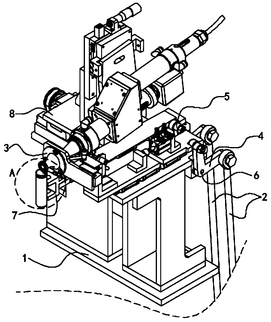
[0004] The invention provides an end cap welding mechanism to solve the problems of poor welding accuracy of existing spot welders and difficulty in inserting lithium-ion battery production automatic lines in the above background; an end cap welding mechanism includes a table; A cam pushing mechanism, a shell clamping mechanism is set above the table, and an end cap clamping mechanism and a laser welding mechanism are respectively set on both sides of the shell clamping mechanism; the electric cam pushing mechanism is set with a first transmission rod and a second Two transmission rods; the electric cam pushing mechanism slides up and down to drive the first transmission rod to swing around the first rotating shaft, and drives the end cap clamping mechanism to move back and forth, so as to realize the fitting block to press the lug to fit the end cap; the said The electric cam pushing mechanism slides up and down to drive the second transmission rod to swing around the first rotating shaft, and drives the shell clamping mechanism to move back and forth to realize clamping the shell; the laser welding mechanism moves through the horizontal transplanting platform and the laser. The planting mechanism adjusts the position of the laser so that the laser light spot of the laser is consistent with the tab and the end cap, ensuring the welding accuracy of the tab and the end cap, and using laser welding to greatly improve the welding efficiency; at the same time, the end cap welding mechanism can be arranged in an array Lithium-ion battery production automatic line, realizing multi-station welding

Method used


Image

  • End cap welding mechanism
  • End cap welding mechanism
  • End cap welding mechanism

Examples


Embodiment Construction

[0030]The following will clearly and completely describe the technical solutions in the embodiments of the present invention with reference to the accompanying drawings in the embodiments of the present invention. Obviously, the described embodiments are only some, not all, embodiments of the present invention. Based on the embodiments of the present invention, all other embodiments obtained by users of ordinary skill in the art without making creative efforts belong to the protection scope of the present invention.

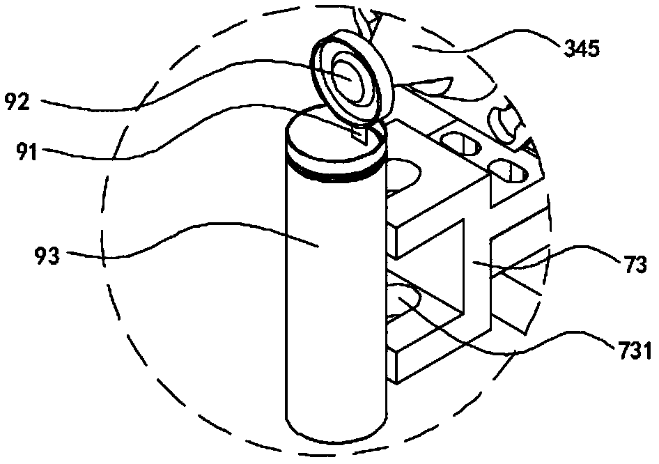
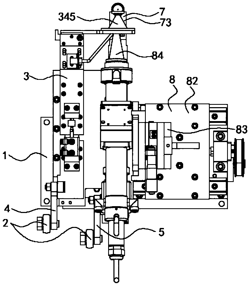
[0031] refer to Figure 1-3 , an end cap welding mechanism, including a platen 1; an electric cam pushing mechanism 2 is arranged below the platen 1, a shell clamping mechanism 7 is set above the platen 1, and both sides of the shell clamping mechanism 7 An end cap clamping mechanism 3 and a laser welding mechanism 8 are provided respectively; the electric cam pushing mechanism 2 is provided with a first transmission rod 4 and a second transmission rod 5; the ele...


PUM


Abstract

The invention discloses an end cap welding mechanism. The end cap welding mechanism comprises a platen, wherein an electric cam push mechanism is arranged below the platen; a housing clamping mechanism is arranged above the platen; the two sides of the housing clamping mechanism are separately equipped with an end cap clamping mechanism and a laser welding mechanism; the electric cam push mechanism is equipped with a first transmission rod and a second transmission rod; the electric cam push mechanism slides up and down for driving the first transmission rod to swing around a first rotary shaft to drive the end cap clamping mechanism to move front and rear, so that a fitting block presses a lug to fit to an end cap; the electric cam push mechanism slides up and down for driving the secondtransmission rod to swing around the first rotary shaft to drive the housing clamping mechanism to move front and rear, so that the clamp clamps the housing; and the laser welding mechanism regulatesthe position of a laser unit through a horizontal transplanting platform and a laser unit transplanting mechanism, so that a laser spot of the laser unit is kept consistent with the lug and the end cap, and therefore, welding precision between the lug and the end cap is guaranteed.

Description

technical field [0001] The invention relates to the field of end cap welding, in particular to an end cap welding mechanism. Background technique [0002] With the increasing shortage of renewable energy in the world, lithium-ion batteries have received more and more attention as a clean energy source; currently lithium-ion batteries are widely used in mobile phones, notebooks, backup power supplies, UPS, power tools, digital products and other products ; When a lithium-ion battery is charged, lithium ions are generated on the positive electrode of the battery, and the generated lithium ions move to the negative electrode through the electrolyte; while the carbon as the negative electrode has a layered structure, it has many micropores, and the lithium ions that reach the negative electrode The ions are embedded in the micropores of the carbon layer, and the more lithium ions are embedded, the higher the charging capacity. [0003] During the production process of lithium-i...

Claims


Application Information

Patent Timeline
IPC IPC(8): B23K26/22B23K26/70B23K37/04B23K26/08H01M50/00H01M50/147H01M50/271
CPCB23K26/0869B23K26/22B23K26/702B23K37/0435
Inventor 何茂水马益金张中
Owner HUIZHOU CHENGTAI AUTOMATION TECH CO LTD
Learn More