Material part quick demolding structure of anchor chain transverse stop punch

A technology of punching and demoulding, which is applied in the field of anchor chains, can solve the problems of unsatisfactory and reliable removal of parts 50, waste of return time, scratching and other problems, and achieve easy cooperation with automated operations, easy installation, and simplified components Effect

Active Publication Date: 2018-12-21
青岛天顺达机械制造有限公司
View PDF7 Cites 0 Cited by
  • Summary
  • Abstract
  • Description
  • Claims
  • Application Information

AI Technical Summary

Problems solved by technology

[0004] This demoulding design has obvious adverse effects on the working efficiency
Because the stripping action of the push rod 60 will only be executed when the hammer 40 reaches the top dead center, and when the limiting rod 61 has touched the stopper 62, the push rod 60 and the material 50 cannot be connected. Disengagement, so the return journey [rising process] time of the hammer 40 is spent on the limit rod 61 waiting for the hammer 40 to descend. The waste of operation time will reduce the speed of automation. Accumulated, the waste of return time will significantly reduce the quantification efficiency
[0005] And it is worth noting that when the processing speed is fast, since the aforementioned material stripping is carried out when the punch 40 reaches the top dead center, when the push rod 60 is stripped, the rapid decline of the punch 40 and the die head 42 is carried out. During the stroke, the descending speed of the material 50 is slower than that of the die head 42 and is often caught by the die head 42. The stripping action of the material 50 cannot be achieved satisfactorily and reliably, so it cannot keep up with the rapid pace of automatic quantification

Method used


Image

  • Material part quick demolding structure of anchor chain transverse stop punch
  • Material part quick demolding structure of anchor chain transverse stop punch
  • Material part quick demolding structure of anchor chain transverse stop punch

Examples


Embodiment Construction

[0016] The specific implementation manner of the present invention will be described in detail below in conjunction with the accompanying drawings.

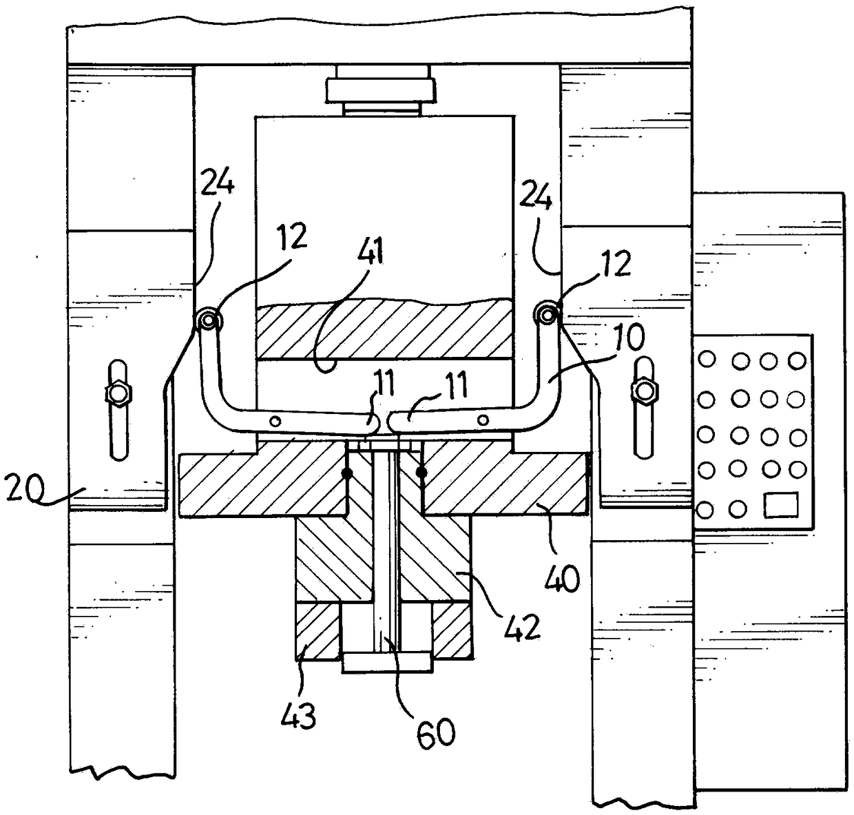
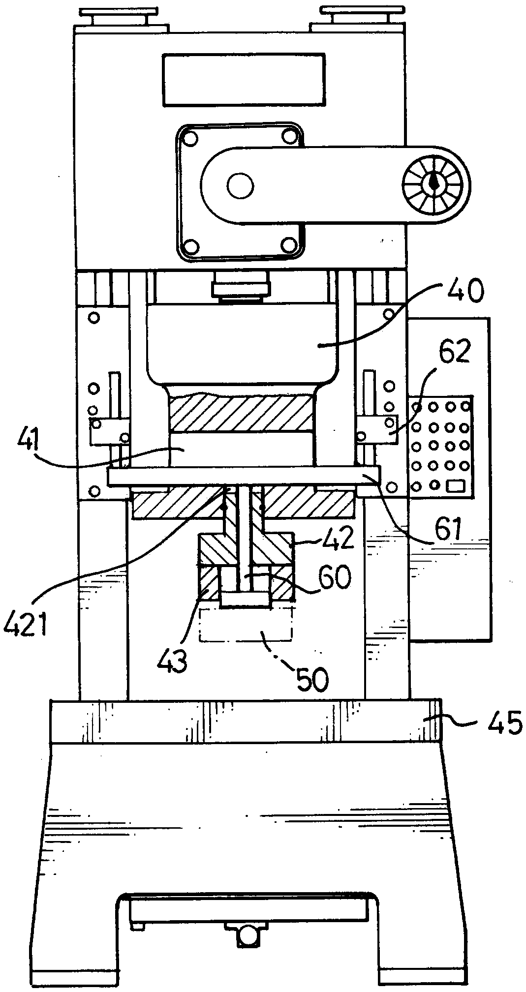
[0017] like figure 1 and 2 As shown, a fast demoulding structure of the material of the anchor chain crosspiece punch press has little change to the punch itself, so the positions of the die head 42, the upper die 43, and the hammer 40 will not change, and the main change makes the material 50 The demoulding efficiency is more effective and faster.

[0018] It includes a pair of stripping arms 10 pivotally arranged in the long hole area 41 of the die head 42, and orientation blocks 20 fixed on both sides of the punch body. The stripping arm 10 is a nearly L-shaped support arm bar, the vertical end is slightly tilted towards the outside, and the end of the vertical end is recessed to pivotally install a guide wheel 12 therebetween. The guide wheel 12 can be a wheel or a bearing. The horizontal end is the impact end 11; the ori...


PUM


Abstract

The invention relates to the field of anchor chains, in particular to a material part quick demolding structure of an anchor chain transverse stop punch. A transverse long hole area is formed in a punch hammer; the punch hammer is connected with a mold head; a pushing rod and a pair of molding arms are placed in the mold head; the demolding arms are similarly L-shaped support arm rods, movable wheel type guide wheels are pivoted at the tail ends of vertical ends, and horizontal ends are collision ends; orienting blocks are locked on a punch body and near two sides of the punch hammer; the inner sides of the orienting blocks are near the punch hammer; a lower corner with a slight upper arc is formed in a non-rising normal state position of the punch hammer; the lower corner aslant extends to gradually approach an inclined wall of the punch hammer; and the upper part of the inclined wall is a vertical wall type priming wall. The demolding design cannot cause great framework change of thepunch body, and is easy to install, low in cost and simple in element; and through the structure with practicability and advancement, the excellent effect easier to cooperate with automatic operationis achieved.

Description

technical field [0001] The invention relates to the field of anchor chains, in particular to a rapid demoulding structure for material parts of an anchor chain transom punching machine. Background technique [0002] like image 3 As shown, most of the machines for processing and forming anchor chain crosspieces use punching machines. The punching machine uses the principle of the connecting rod to cooperate with the slider to form an up and down movement, so that the upper mold can press the plate on the lower mold with the help of momentum, remove excess waste or form a specific workpiece shape. The punching machine needs to cooperate with the push rod to separate the material from the die head. The general use form is as follows image 3 As shown, the punch press is equipped with a lower die in the workbench, and the hammer 40 traverses through a long hole area 41 near the lower part to place a limiting rod 61 in the long hole area 41. Fasten a die head 42, the bottom sur...

Claims


Application Information

Patent Timeline
Patent Type & Authority Applications(China)
IPC IPC(8): B21D45/04
CPCB21D45/04
Inventor 宋修君周家波周家淳兰孝柱黄品
Owner 青岛天顺达机械制造有限公司
Why Eureka
Try Eureka