Pushing driving device of mechanical pushing centrifuge

A driving device and centrifuge technology, applied in the direction of centrifuges, etc., can solve the problems of high manufacturing and maintenance costs, complex positioning and guiding structure of the pushing shaft, and complex structure, so as to achieve low manufacturing and maintenance costs and convenient procurement and maintenance , the effect of simple structure

Active Publication Date: 2018-12-21
XIANGTAN HUIBO CENTRIFUGE
View PDF18 Cites 1 Cited by
  • Summary
  • Abstract
  • Description
  • Claims
  • Application Information

AI Technical Summary

Problems solved by technology

[0004] The invention solves the problem of complex structure, high manufacturing and maintenance costs, complicated positioning and guiding structure of the pusher shaft, and easy oil leakage of the main bearing in the prior art, and the pusher driving device of the present invention realizes that the original separation principle is not changed. At the same time change the reciprocating motion drive mode of the drum
The invention also overcomes the problem that the structure of the pushing piece is complex and the material is easily leaked into the mother liquor during centrifugal treatment

Method used


Image

  • Pushing driving device of mechanical pushing centrifuge
  • Pushing driving device of mechanical pushing centrifuge
  • Pushing driving device of mechanical pushing centrifuge

Examples


specific Embodiment

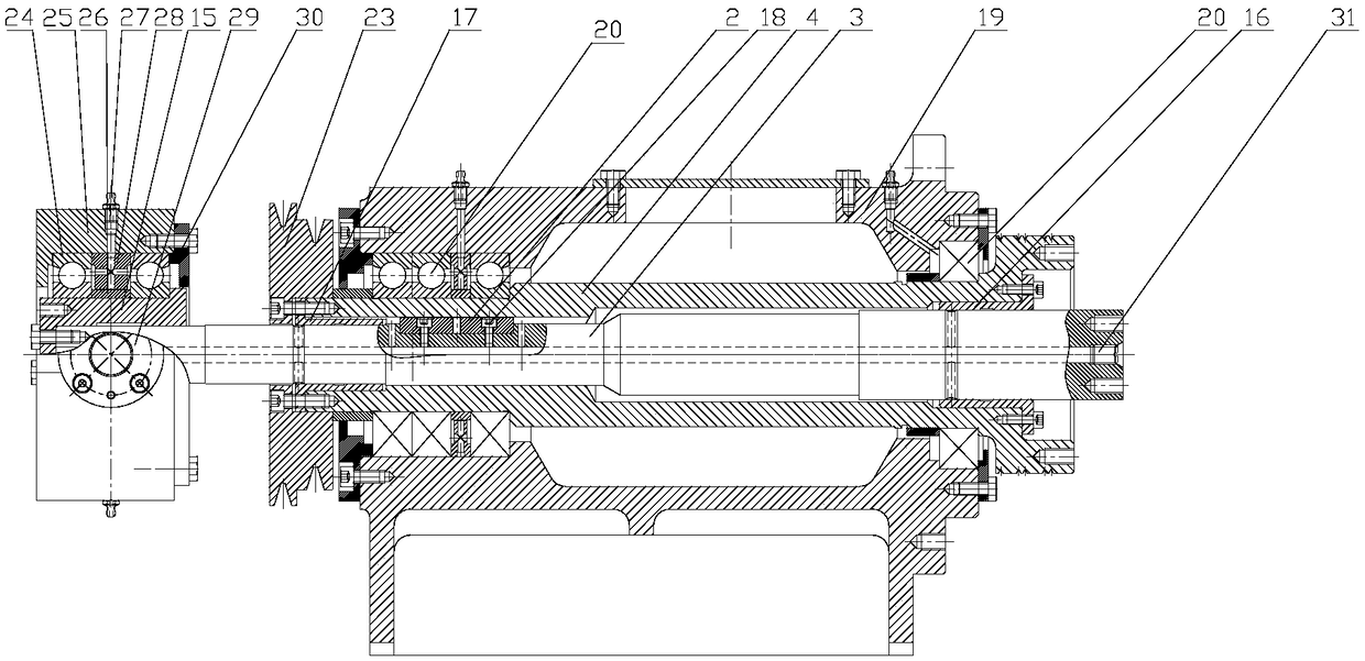
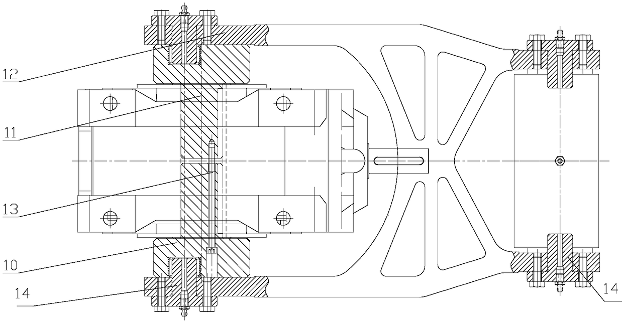
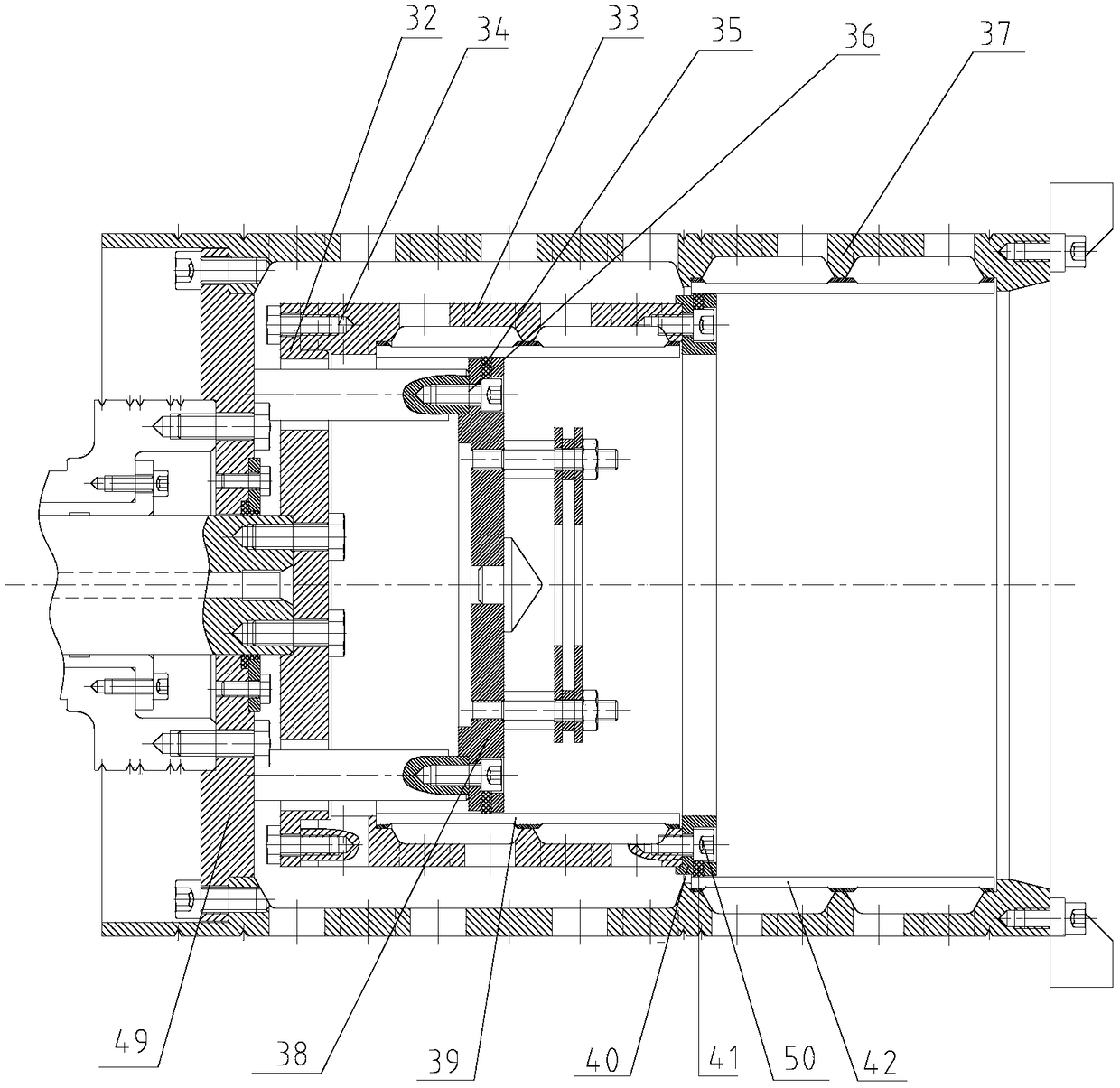
[0026] Such as Figure 1-5 As shown, a kind of two-stage mechanical pusher centrifuge pusher driving device according to the present invention includes a motor, a reducer 1, a transmission device, a pusher bearing assembly, a guide key 2, a pusher shaft 3, a hollow shaft 4 and The primary drum assembly, the motor includes a main motor 5 and an auxiliary motor 6, the main motor 5 is connected with a rotating driving wheel 21, and the rotating driving wheel 21 is connected with a connecting shaft 2 22, and the connecting shaft 2 22 The other end is connected with the rotating driven wheel 23, and the rotating driven wheel 23 is connected with the hollow shaft 4, and the main motor 5 drives the hollow shaft 4 to drive the main bearing to rotate; the auxiliary motor 6 is connected with a pushing driving wheel 7. The pusher driving wheel 7 is connected with a connecting shaft 8, the other end of the connecting shaft 8 is connected with the pusher driven wheel 9, and the pusher driv...


PUM


Abstract

The invention discloses a pushing driving device of a mechanical pushing centrifuge, and relates to the technical field of mechanical pushing centrifuges. The pushing driving device of the mechanicalpushing centrifuge adopts a motor driving speed reducer to drive a transmission device to move front and back; the transmission device and a connected shaft sleeve are rotated; the shaft sleeve drivesa pushing shaft to slide back and forth; a guide key is arranged between the pushing shaft and a hollow shaft, so that the pushing shaft slides back and forth in the hollow shaft in a path of the guide key; the pushing shaft drives a first-grade rotating drum bottom to drive a first-grade rotating drum to move back and forth; and a pushing piece is of a fan annular structure to stop materials from leaking in mother liquor in centrifugal treatment. The pushing driving device of the mechanical pushing centrifuge is simple in structure, lower in production and maintenance cost and simple in positioning and guide structure of the pushing shaft, prevents the oil leakage phenomenon, can achieve the effects needed by the reciprocating motion of the first-grade rotating drum; the pushing piece issimple in structure; and materials are not easy to leak into the mother liquor in centrifugal treatment.

Description

technical field [0001] The invention belongs to the technical field of a mechanical pushing centrifuge, and in particular relates to a pushing driving device of a mechanical pushing centrifuge. Background technique [0002] The pusher driving device in the mechanical pusher centrifuge is usually divided into two types: mechanical or hydraulic. The pusher drive device rotates at the same speed and in the same direction as the drum, and pushes the material back and forth with the pusher plate. At present, the mechanical pusher driving device uses a speed-regulating motor to drive the reducer, and then uses the eccentric wheel output on the reducer to drive the connecting rod, and the connecting rod is connected with the push rod coupling to make forward and backward motions to achieve the purpose of pushing materials. Although the structure of the device is simple, there is a lot of wear between the mating parts, the pusher shaft cannot be positioned and guided, and the rotati...

Claims


Application Information

Patent Timeline
IPC IPC(8): B04B11/02B04B9/02B04B9/08
CPCB04B9/02B04B9/08B04B11/02
Inventor 王深波颜国良王细枧
Owner XIANGTAN HUIBO CENTRIFUGE
Why Eureka
Try Eureka