
Spiral tool bit mechanism

A technology of spiral and cutter head, applied in the field of spiral cutter head mechanism, can solve the problems of low efficiency and high labor intensity, and achieve the effect of reducing weight, reasonable structure and reducing propulsion resistance

Active Publication Date: 2018-12-21
XIANGYA HOSPITAL CENT SOUTH UNIV
View PDF10 Cites 0 Cited by
  • Summary
  • Abstract
  • Description
  • Claims
  • Application Information

AI Technical Summary

Problems solved by technology

[0002] When orthopedic surgeons obtain autologous bone during surgery, they need to remove soft tissues such as muscle and fascia on the bone surface. Most of them use a scalpel to remove the bone and flesh. This method is labor-intensive and inefficient.

Method used


Image

  • Spiral tool bit mechanism

Examples


Embodiment Construction

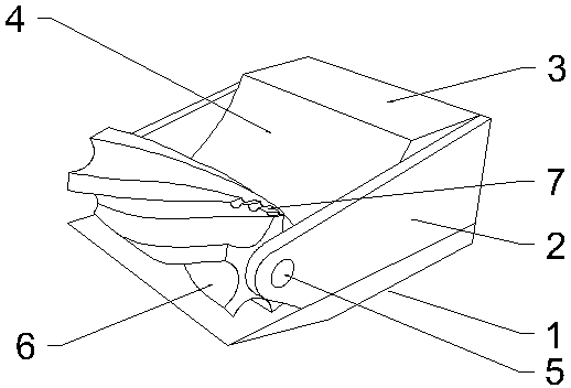
[0011] Below in conjunction with all accompanying drawings the present invention will be further described, and preferred embodiment of the present invention is: see appended figure 1 , a kind of spiral cutter head mechanism described in the present embodiment comprises bottom plate 1, side plate 2, shovel seat 3, and bottom plate 1 is rectangular, and the bottom of one end of its length direction is provided with inclined guide surface, and the end of guide surface is higher It is located at the end of the bottom plate 1, and the side plate 2 is two pieces, which are respectively fixed on both sides of the top of the bottom plate 1 in the length direction, and the shovel seat 3 is fixed on the other end of the bottom plate 1 in the length direction. The two sides of the seat 3 are connected and fixed with the corresponding side plates 2, and the shovel seat 3 located on one side of the guide surface is inclined to extend forward and downward to form an arc-shaped shovel surfac...


PUM


Abstract

The invention provides a spiral tool bit mechanism. The mechanism comprises a bottom plate, side plates and a shovel base, wherein the bottom plate is rectangular, an inclined guide surface is arranged at the bottom of one end of the bottom plate in the length direction, and the higher end of the guide surface is located at the end of the bottom plate; the two side plates are fixed to two sides ofthe top of the bottom plate respectively, and the shovel base is fixed at the other end of the bottom plate; the two sides of the shovel base are fixedly connected with the corresponding side plates,and the portion, on one side of the guide surface, of the shovel base inclines to the lower front portion and extends to form an arc-shaped shovel surface; a cutter shaft is movably hinged between the two side plates above the guide surface, one end of the cutter shaft penetrates through the side plates and is connected with a motor, and a spiral convex rib is arranged on the surface of the cutter shaft; a concave-convex cutting edge is formed in the surface of the convex rib, and a material shoveling channel is reserved between the cutting edge and the surface of the bottom plate; the lowestpart of the shovel surface extends into the material shoveling channel. According to the scheme, the structure is reasonable, and the meat stripping effect is good.

Description

technical field [0001] The invention relates to the technical field of medical instruments, in particular to a spiral cutter head mechanism. Background technique [0002] When orthopedic surgeons obtain autologous bone during surgery, they need to remove soft tissues such as muscle and fascia on the bone surface. Most of them use a scalpel to remove the bone and flesh. This method is labor-intensive and inefficient. Contents of the invention [0003] The purpose of the present invention is to overcome the deficiencies of the prior art and provide a spiral cutter head mechanism with reasonable structure and good peeling effect. [0004] In order to achieve the above object, the technical solution provided by the present invention is: a spiral cutter head mechanism, which includes a base plate, a side plate, and a shovel seat, the base plate is rectangular, and the bottom at one end of its length direction is provided with an inclined guide surface The higher end of the gui...

Claims


Application Information

Patent Timeline
Patent Type & Authority Applications(China)
IPC IPC(8): A61B17/3207
CPCA61B17/320758A61B2017/320775
Inventor 王锡阳刘政张义鲁武韵琦李伟伟肖骁王艺霖沈孟奎
Owner XIANGYA HOSPITAL CENT SOUTH UNIV
Learn More