
An electrical cabinet with an airflow circulation device

A technology of air circulation and electrical cabinets, which is applied in the field of electrical cabinets, can solve problems such as large space occupation, high equipment cost, and influence on the insulation performance of electrical components, and achieve the effect of satisfying heat dissipation and ensuring the protection level

Active Publication Date: 2018-12-18
XEMC WINDPOWER CO LTD
View PDF6 Cites 2 Cited by
  • Summary
  • Abstract
  • Description
  • Claims
  • Application Information

AI Technical Summary

Problems solved by technology

The first way is to install air supply and exhaust fans on the cabinet. When the fan starts, the colder air outside the cabinet is sent into the inside of the cabinet, and the hotter air inside the cabinet is discharged. This method has low cost and good heat dissipation effect. Obviously, but the biggest disadvantage is that the dust and moisture in the air outside the cabinet will inevitably enter the interior of the cabinet, which will easily affect the insulation performance of electrical components
[0004] The second way is to use radiators, such as air-water, air-air, and oil-air radiators. This method can ensure the IP protection level of the unit, but the biggest disadvantage is the high equipment cost, which takes up big space

Method used


Image

  • An electrical cabinet with an airflow circulation device
  • An electrical cabinet with an airflow circulation device
  • An electrical cabinet with an airflow circulation device

Examples


Embodiment Construction

[0017] The present invention will be further described below in conjunction with drawings and embodiments.

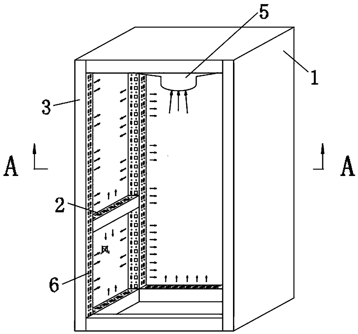
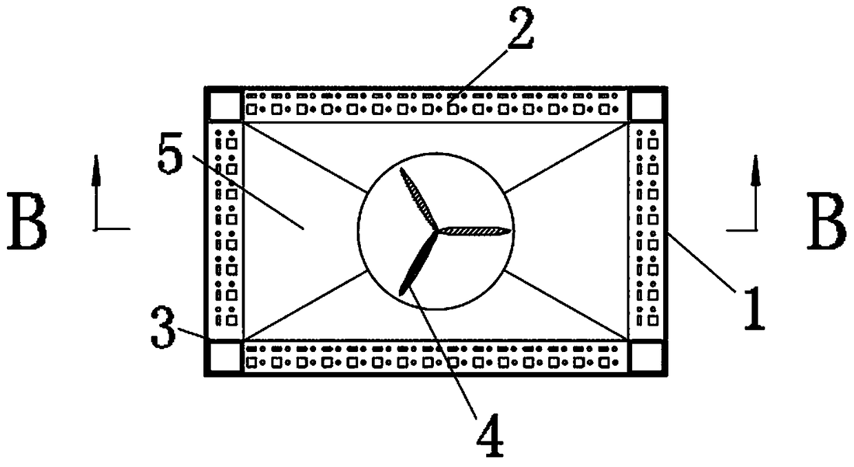
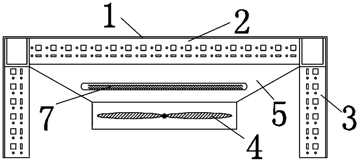
[0018] Referring to the accompanying drawings, an electrical cabinet with an airflow circulation device includes a panel shell 1, a beam 2, a vertical beam 3, a fan 4, and a heater 7. The panel shell 1 is arranged on a frame composed of the beam 2 and the vertical beam 3. An airtight cabinet is formed on the outside, and the air inlet cover 5 is also included. Both the vertical beam 3 and the cross beam 2 are hollow structures with hollow passages inside and are provided with a plurality of installation holes 6, and the installation holes 6 are also used as the air outlet of the hollow passage. , in order to facilitate the processing of the vertical beam 3, the installation holes provided on the vertical beam 3 are equidistant installation holes 6, and in order to facilitate the heat dissipation of the hot air, a plug 8 is also included, and the plug 8 is used to seal so...


PUM


Abstract

The invention relates to an electrical cabinet with an air flow circulating device, include a plate shell, vertical beam, Fan, air inlet cover, the plate and shell are arranged on the outside of the frame composed of the cross beam and the vertical beam to form a sealed cabinet body, The vertical beam and the cross beam are both hollow structures, and are provided with an installation hole and anair outlet hole. The fan is arranged on the upper part of the cabinet body. The air outlet of the fan sucking hot air from the cabinet is connected with the air inlet of the air inlet cover, and the air outlet of the air inlet cover is communicated with the hollow channel of the vertical beam from the upper part of the vertical beam. The invention introduces the hot air in the fan suction cabinetinto the vertical beam through the air inlet cover, An air duct is formed in the inside of the cabinet to realize circulating flow inside the cabinet, and hot air is exchanged with the outside througha metal plate and shell, so that special heat exchange equipment is not required to be added, and the external air of the cabinet body is not required to be sucked into the cabinet body to meet the heat dissipation effect, and the protection level of the cabinet body is ensured.

Description

technical field [0001] The invention relates to an electrical cabinet body, in particular to an electrical cabinet with an air circulation device. Background technique [0002] The electrical cabinet is generally composed of beams and vertical beams, and the outside is equipped with a plate shell to form a square cabinet body. The vertical beams and beams are hollow structures, and equidistant fixing holes are opened on the surface as fixing holes for fixing component mounting plates. When electrical devices are working with electricity, they will generate heat at the same time. In order to ensure that the generated heat does not accumulate in the cabinet, the temperature will rise beyond the normal operating temperature of the electrical devices. Generally, a cooling system is installed on the cabinet body. [0003] At present, the heat dissipation system of the electrical cabinet generally adopts two methods. The first way is to install air supply and exhaust fans on the...

Claims


Application Information

Patent Timeline
Patent Type & Authority Applications(China)
IPC IPC(8): H05K7/20
CPCH05K7/20572
Inventor 刘乔刘亚
Owner XEMC WINDPOWER CO LTD
Learn More