A data reading method, device, equipment and readable storage medium

A technology for reading and receiving data, applied in the storage field, can solve the problems of increasing the read delay of the flash memory controller and the flash memory chip, increasing the load of the flash memory chip and the controller, and increasing the load of the off-chip communication link. The effect of low precision requirements, speeding up data reading, and ensuring data reliability

Active Publication Date: 2021-08-13
GUANGDONG UNIV OF TECH
View PDF7 Cites 0 Cited by
  • Summary
  • Abstract
  • Description
  • Claims
  • Application Information

AI Technical Summary

Problems solved by technology

Read amplification will increase the read latency of the flash controller and flash chip, and increase the load between the flash chip and the controller
2. Fine texture detection. In order to provide higher precision and obtain more effective compensation values, fine texture detection technology is used. For example, the data stored in flash memory is 2 bits / cell (bit / cell), and 4 bits or higher detection accuracy is required. Read the threshold voltage of each unit, which will increase the load of the off-chip communication link, reduce the reading speed, and also cause a relatively large delay

Method used


Image

  • A data reading method, device, equipment and readable storage medium
  • A data reading method, device, equipment and readable storage medium
  • A data reading method, device, equipment and readable storage medium

Examples


Embodiment 1

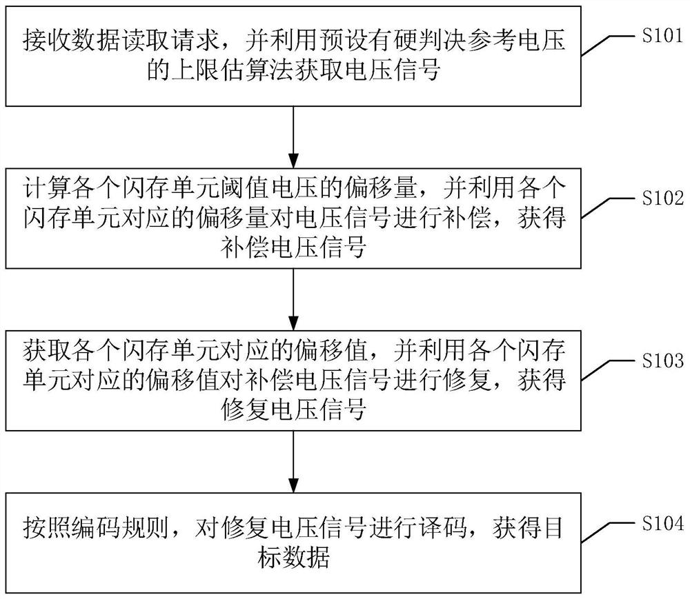
[0055] Please refer to figure 1 , figure 1 It is a flowchart of a data reading method in an embodiment of the present invention, and the method includes the following steps:

[0056] S101 receives a data read request, and obtains a voltage signal by using an upper limit estimation method preset with a hard decision reference voltage.

[0057] Wherein, the voltage signal includes the threshold voltage of each flash memory unit corresponding to the data read request.

[0058] It should be noted that the estimation method listed in the embodiment of the present invention is an upper limit estimation method, and in other embodiments of the present invention, a lower limit estimation method or a median estimation method may also be used. For the convenience of description, the upper limit estimation method is used as an example for description below, and other estimation methods can be referred to accordingly, and will not be repeated here. Each interval limit of the upper limit...

Embodiment 2

[0078] In order to facilitate those skilled in the art to understand the technical solution provided by the embodiment of the present invention, step S103 in the first embodiment above will be described in detail below. Please refer to image 3 , image 3 It is a schematic diagram of the specific acquisition process of the offset value in the embodiment of the present invention.

[0079] S201. Calculate prior information of each interference unit.

[0080] The prior information of the interference unit is calculated, and the signal detection algorithm based on the prior information is used for the threshold voltage movement after conventional post-compensation. Specifically, formula 4, formula 5 and formula 6 can be used to calculate the prior information X of each interference unit:

[0081]

[0082]

[0083]

[0084] Among them, Equation 4 and Equation 5 represent the maximum likelihood estimation algorithm to estimate the distribution parameters, sp represents e...

Embodiment 3

[0112] In order to facilitate those skilled in the art to understand the technical solutions provided by the embodiments of the present invention, the technical solutions provided by the embodiments of the present invention will be described in detail below in conjunction with specific examples and simulation experiments.


PUM


Abstract

The invention discloses a data reading method, which includes: receiving a data reading request, and obtaining a voltage signal by using an upper limit estimation method preset with a hard decision reference voltage; calculating the offset of the threshold voltage of each flash memory unit, and using each The offset corresponding to the flash memory unit compensates the voltage signal to obtain a compensation voltage signal; obtains the offset value corresponding to each flash memory unit, and uses the offset value corresponding to each flash memory unit to repair the compensation voltage signal to obtain a repair voltage signal; According to the encoding rules, the repair voltage signal is decoded to obtain the target data. In the case of ensuring data reliability, the data reading speed can be accelerated, the data reading delay can be reduced, and the processing speed of the computer system can be further improved. The invention also discloses a data reading device, equipment and a readable storage medium, which have corresponding technical effects.

Description

technical field [0001] The present invention relates to the field of storage technology, in particular to a data reading method, device, equipment and readable storage medium. Background technique [0002] Flash memory (Flash memory) is a semiconductor computing device memory with many ideal characteristics, including NOR flash memory and NAND flash memory. Among them, NAND flash memory, due to its non-volatile characteristics, low power consumption, high storage capacity, and portability, its application field extends from personal electronic devices to large-scale data processing centers. Due to the continuous evolution of the manufacturing process, flash memory devices now use 1×nmCMOS transistors and faster read and write processes, so that each flash memory unit can store more than 1bit of data, which is called multi-level flash memory (Multi-Level Cell, MLC ) storage technology. [0003] Due to the special structure of the CMOS transistor, when the storage density of...

Claims


Application Information

Patent Timeline
Patent Type & Authority Patents(China)
IPC IPC(8): G06F3/06
CPCG06F3/0611G06F3/0614G06F3/0679
Inventor 韩国军李艳福彭子帅方毅蔡国发
Owner GUANGDONG UNIV OF TECH
Why Eureka
Try Eureka