
A Circumferential Guidance Mechanism Based on Roberts Mechanism

A guiding mechanism and circular technology, applied in the direction of mechanical equipment, bearings for rotating motion, rotating parts that resist centrifugal force, etc.

Active Publication Date: 2021-08-20
CHANGCHUN INST OF OPTICS FINE MECHANICS & PHYSICS CHINESE ACAD OF SCI
View PDF10 Cites 0 Cited by
  • Summary
  • Abstract
  • Description
  • Claims
  • Application Information

AI Technical Summary

Problems solved by technology

The application of flexible structures to guiding mechanisms is currently mainly focused on linear guiding mechanisms, and there is no report on the use of flexible structures in circular guiding mechanisms.

Method used


Image

  • A Circumferential Guidance Mechanism Based on Roberts Mechanism
  • A Circumferential Guidance Mechanism Based on Roberts Mechanism
  • A Circumferential Guidance Mechanism Based on Roberts Mechanism

Examples


Embodiment Construction

[0023] In order to make the object, technical solution and advantages of the present invention clearer, the present invention will be further described in detail below in conjunction with the accompanying drawings and specific embodiments. It should be understood that the specific embodiments described here are only used to explain the present invention, but not to limit the present invention.

[0024] In describing the present invention, it should be understood that the terms "center", "longitudinal", "transverse", "length", "width", "thickness", "upper", "lower", "front", " Back", "Left", "Right", "Vertical", "Horizontal", "Top", "Bottom", "Inner", "Outer", "Clockwise", "Counterclockwise", "Axial", The orientation or positional relationship indicated by "radial", "circumferential", etc. is based on the orientation or positional relationship shown in the drawings, and is only for the convenience of describing the present invention and simplifying the description, rather than ...


PUM


Abstract

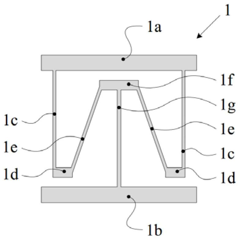
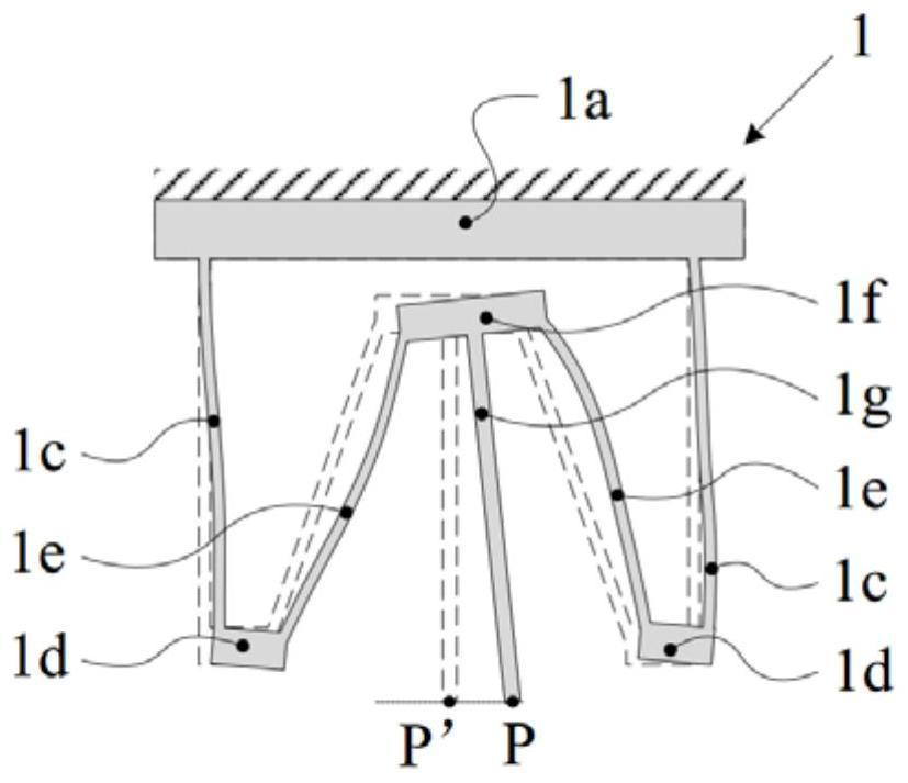
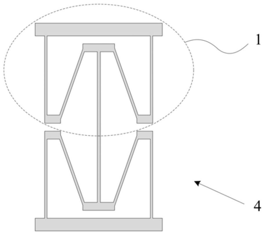
The invention provides a circular guiding mechanism based on the Roberts mechanism, comprising: an outer connecting ring; an inner connecting ring, the inner connecting ring is coaxial with the outer connecting ring; There are a plurality of Roberts mechanisms connecting the outer connecting ring and the inner connecting ring as one. The circular guide mechanism based on the Roberts mechanism provided by the present invention is an integrated structure, without the need to process multiple parts for assembly, and can be completed by using the wire electric discharge cutting process, the processing is simple, and it is easy to achieve high processing accuracy, which is beneficial Improve guidance accuracy.

Description

technical field [0001] The invention relates to the technical field of a bearingless precision circular guide mechanism, in particular to an integrated flexible circular guide mechanism based on a Roberts mechanism. Background technique [0002] In equipment with precise circular motion such as radar antennas, theodolites, and precision instruments, it is often necessary to use a circular guiding mechanism to improve the accuracy of circular motion and reduce motion errors in non-moving directions. Commonly used circular guide mechanisms are rolling bearings and joint bearings. When these bearings are in use, lubricants are generally required, so that there is a possibility of chemical contamination in the equipment. When the bearing is running, the components in the bearing rub against each other, which makes it easy for particle pollution to mix into the equipment. Due to the construction principle of the bearing, there is a gap between the components in the bearing, whi...

Claims


Application Information

Patent Timeline
Patent Type & Authority Patents(China)
IPC IPC(8): F16C27/00
CPCF16C27/00F16C2300/40F16C2370/20
Inventor 郭抗孙振陈华男倪明阳隋永新杨怀江
Owner CHANGCHUN INST OF OPTICS FINE MECHANICS & PHYSICS CHINESE ACAD OF SCI
Learn More