
Steam turbine chassis and steam turbine

A steam turbine and chassis technology, which is applied to machines/engines, mechanical equipment, engine components, etc., can solve problems such as difficult adjustment of the center, and achieve the effects of reducing difficulty, simple and practical processing and installation processes, and shortening processing cycles.

Pending Publication Date: 2018-12-18
CHINA CHANGJIANG ENERGY CORP GROUP
View PDF8 Cites 1 Cited by
  • Summary
  • Abstract
  • Description
  • Claims
  • Application Information

AI Technical Summary

Problems solved by technology

[0003] The purpose of the present invention is to provide a steam turbine chassis and a steam turbine, which can solve the problem that the center is difficult to adjust when the steam turbine is installed

Method used


Image

  • Steam turbine chassis and steam turbine
  • Steam turbine chassis and steam turbine
  • Steam turbine chassis and steam turbine

Examples


Embodiment 1

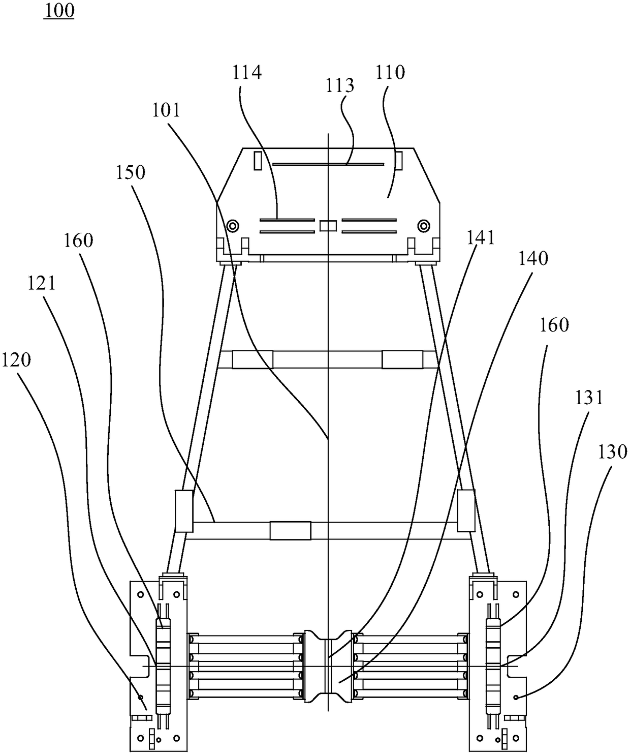
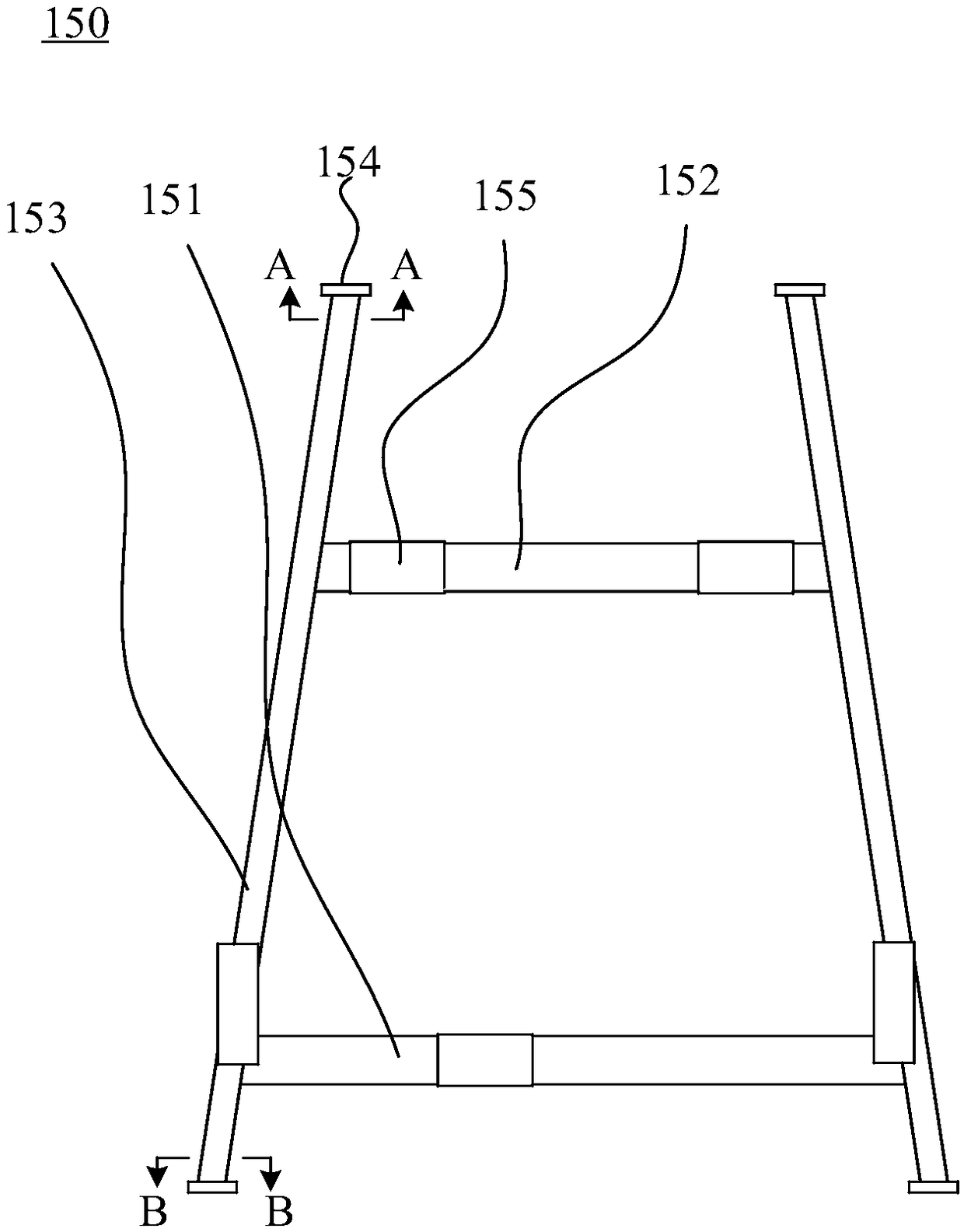
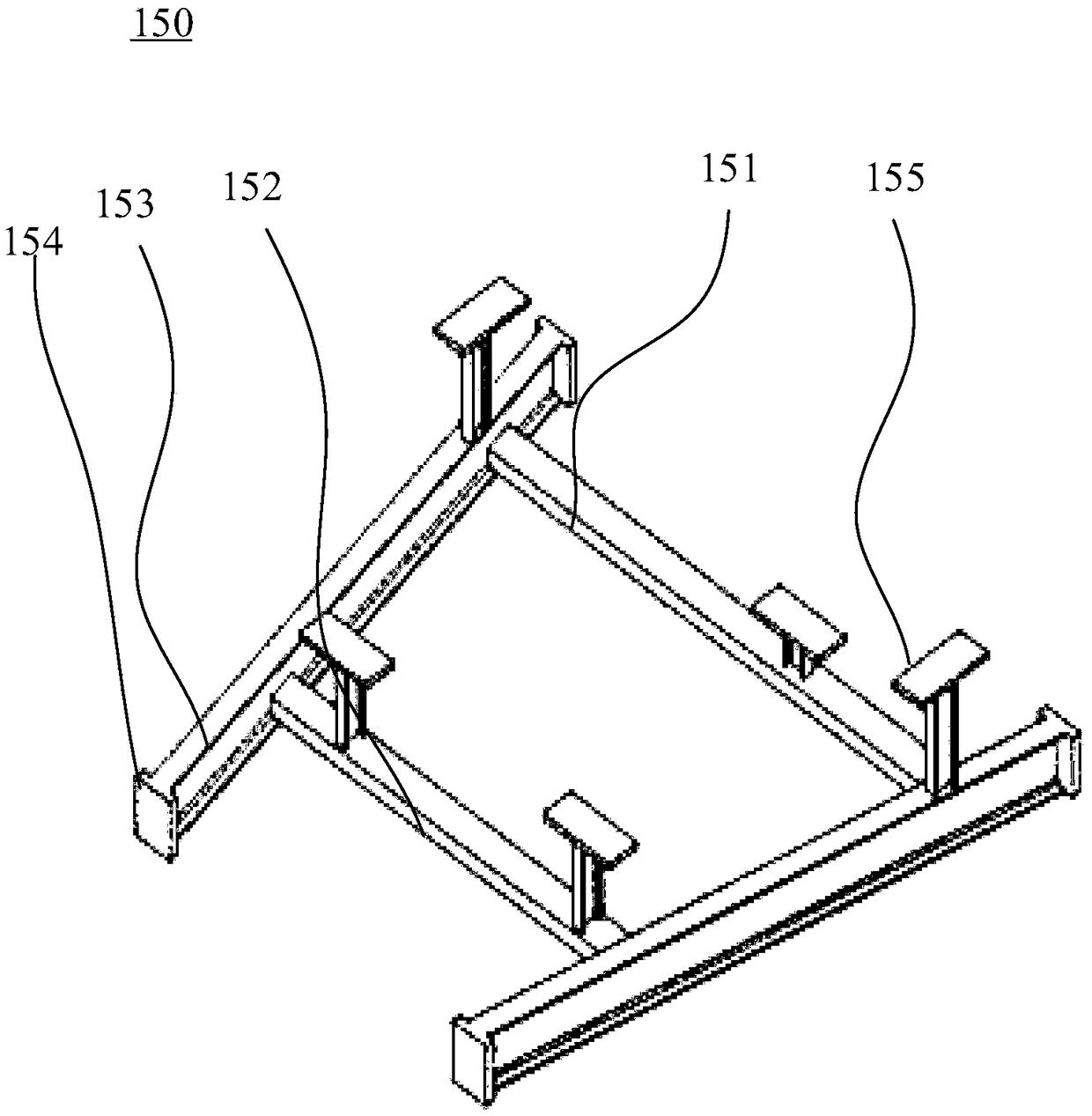
[0032] Please refer to figure 1 , the embodiment of the present invention provides a steam turbine chassis 100, including a first deck 110, a second deck 120, a third deck 130, a fourth deck 140 and a support assembly 150, the support assembly 150 includes symmetrically arranged in the center of the chassis There are two angle steels 153 on both sides of the line 101 in a figure-eight shape and a first beam 151 and a second beam 152 arranged between the two angle steels 153, the first platen 110 is detachably connected to the ends of the two angle steels 153, The second platform 120 and the third platform 130 are detachably connected with two angle steels 153 respectively; The second platform 120 and the third platform 130 are detachably connected.

[0033] It should be noted that, first, if figure 1 As shown, the two angle steels 153 arranged in a figure-eight shape have four ends in total, and the first platen 110 is connected with the two ends on the same side of the two ...

Embodiment 2

[0061] An embodiment of the present invention provides a steam turbine, including a steam turbine body and the above-mentioned steam turbine chassis 100 , and the steam turbine body is installed on the steam turbine chassis 100 .

[0062] The steam turbine provided by the embodiment of the present invention has a detachable steam turbine chassis 100, so that each part of the steam turbine chassis 100 becomes an independent device, which can be processed separately and connected by bolts for assembly and disassembly. The detachable steam turbine chassis 100 is manufactured And the flexible assembly ensures the installation accuracy, installation progress and operation quality of the complete steam turbine, which makes the complete steam turbine have the characteristics of compact structure and high working efficiency.


PUM


Abstract

The invention provides a steam turbine chassis and a steam turbine and belongs to the technical field of steam turbines. The steam turbine chassis comprises a first table board, a second table board,a third table board, a fourth table board and a supporting assembly. The supporting assembly comprises two steel angles symmetrically arranged on the two sides of the center line of the chassis in a splayed mode, a first cross beam and a second cross beam, wherein the first cross beam and the second cross beam are arranged between the two steel angles. The first table board is detachably connectedwith the ends of the ends of the two steel angles. The second table board and the second table board are detachably connected with the two steel angles correspondingly. The fourth table board is arranged between the second table board and the third table board. The fourth table board is detachably connected with the second table board and the third table board. According to the steam turbine chassis, the first table board, the second table board and the third table board are detachably connected with the supporting assembly to form the assembly type gas turbine chassis; the machining cycle ofthe steam turbine chassis is shortened; the installation difficulty of the table boards is reduced; and thus, the steam turbine chassis is simple and practical in machining and installation process,safe and reliable, and the center of the steam turbine chassis can be adjusted conveniently.

Description

technical field [0001] The invention relates to the technical field of steam turbines, in particular to a steam turbine chassis and a steam turbine. Background technique [0002] At present, domestic steam turbine manufacturers mainly use the traditional integral chassis structure, which is complex in processing and assembly, and the installation process is cumbersome. The front and rear platens and support beams are welded into a whole, it is difficult to adjust the center, and the installation cycle is long. Contents of the invention [0003] The object of the present invention is to provide a steam turbine chassis and a steam turbine, which can solve the problem that the center is difficult to adjust when the steam turbine is installed. [0004] Embodiments of the present invention are achieved like this: [0005] An embodiment of the present invention provides a chassis of a steam turbine, including a first base plate, a second base plate, a third base plate, a fourth...

Claims


Application Information

Patent Timeline
Patent Type & Authority Applications(China)
IPC IPC(8): F01D25/28F01D25/00
CPCF01D25/005F01D25/28
Inventor 乐谦王达君瞿灿隋正彭博
Owner CHINA CHANGJIANG ENERGY CORP GROUP
Learn More