
Combined cutterhead of rectangular top pipe heading machine

A rectangular pipe jacking and tunneling machine technology, which is applied to mining equipment, earthwork drilling, tunnels, etc., can solve the problems of enhancing the resistance of the excavation surface of the rectangular cylinder, fracture of the web, insufficient support strength, etc., and achieve comprehensive pipeline development. The effect of digging and advancing, increasing the area and strength, and improving the ability to resist pressure

Pending Publication Date: 2018-12-18
淮南中泰矿山装备制造有限公司
View PDF0 Cites 1 Cited by
  • Summary
  • Abstract
  • Description
  • Claims
  • Application Information

AI Technical Summary

Problems solved by technology

[0002] Rectangular pipe jacking machine is an effective tool for excavating pipelines and tunnels through underground excavation construction methods, and the cutter head is the primary tool for pipe jacking machine to fully excavate pipelines, but in the prior art more is used A single cutter head has low excavation efficiency, and the combined cutter head on the market has insufficient support strength, which is very easy to cause the spokes (that is, spokes) to break during the excavation process. At the same time, the outer peripheral guardrail of the excavation surface of the rectangular cylinder lacks support. The structure is easy to deform so that the peripheral knife on the front side is deformed, thereby enhancing the propulsion resistance of the excavation surface of the rectangular cylinder, so it needs to be improved

Method used


Image

  • Combined cutterhead of rectangular top pipe heading machine
  • Combined cutterhead of rectangular top pipe heading machine
  • Combined cutterhead of rectangular top pipe heading machine

Examples


Embodiment Construction

[0020] The following will clearly and completely describe the technical solutions in the embodiments of the present invention with reference to the accompanying drawings in the embodiments of the present invention. Obviously, the described embodiments are only some, not all, embodiments of the present invention. Based on the embodiments of the present invention, all other embodiments obtained by persons of ordinary skill in the art without making creative efforts belong to the protection scope of the present invention.

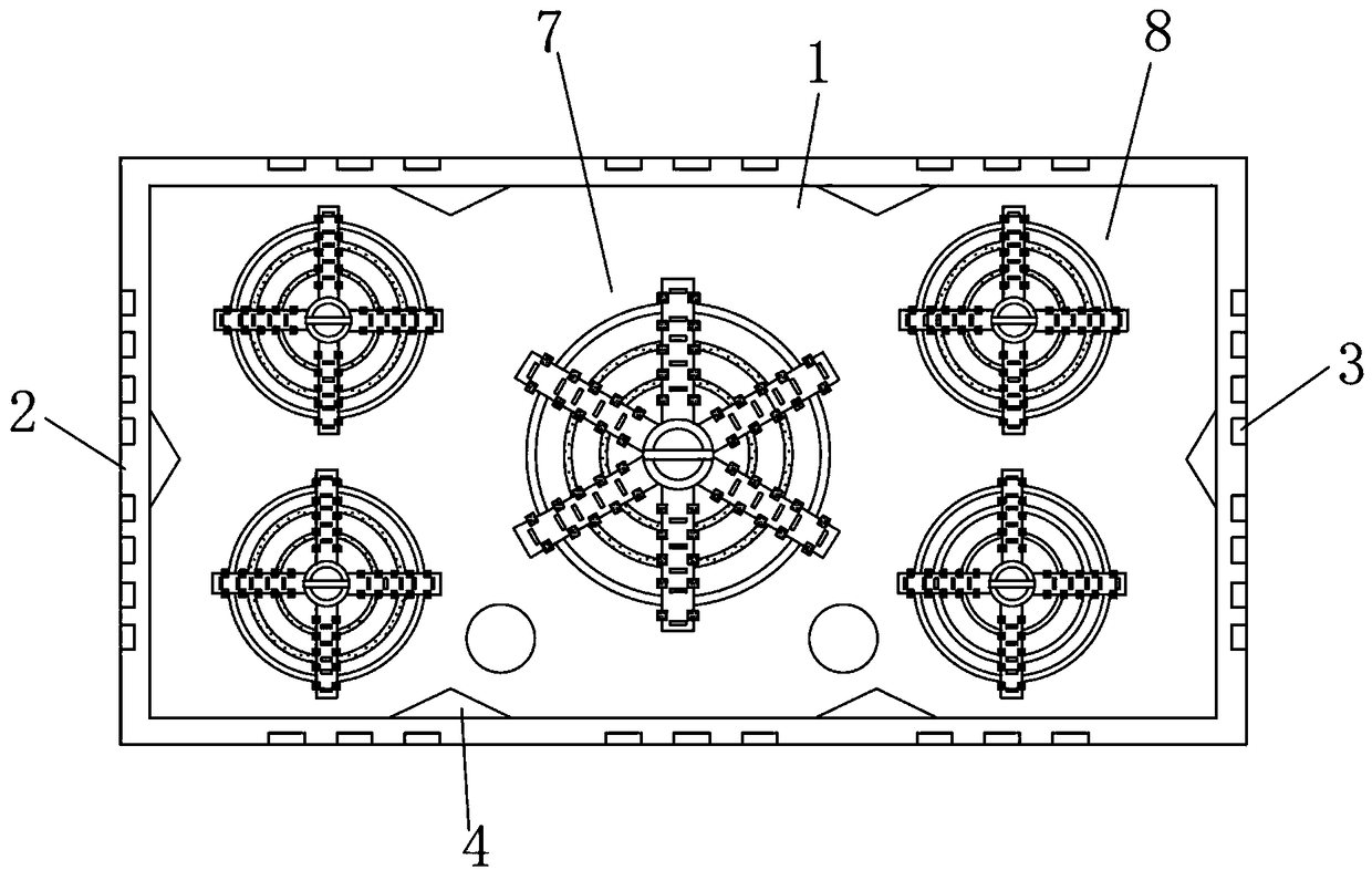
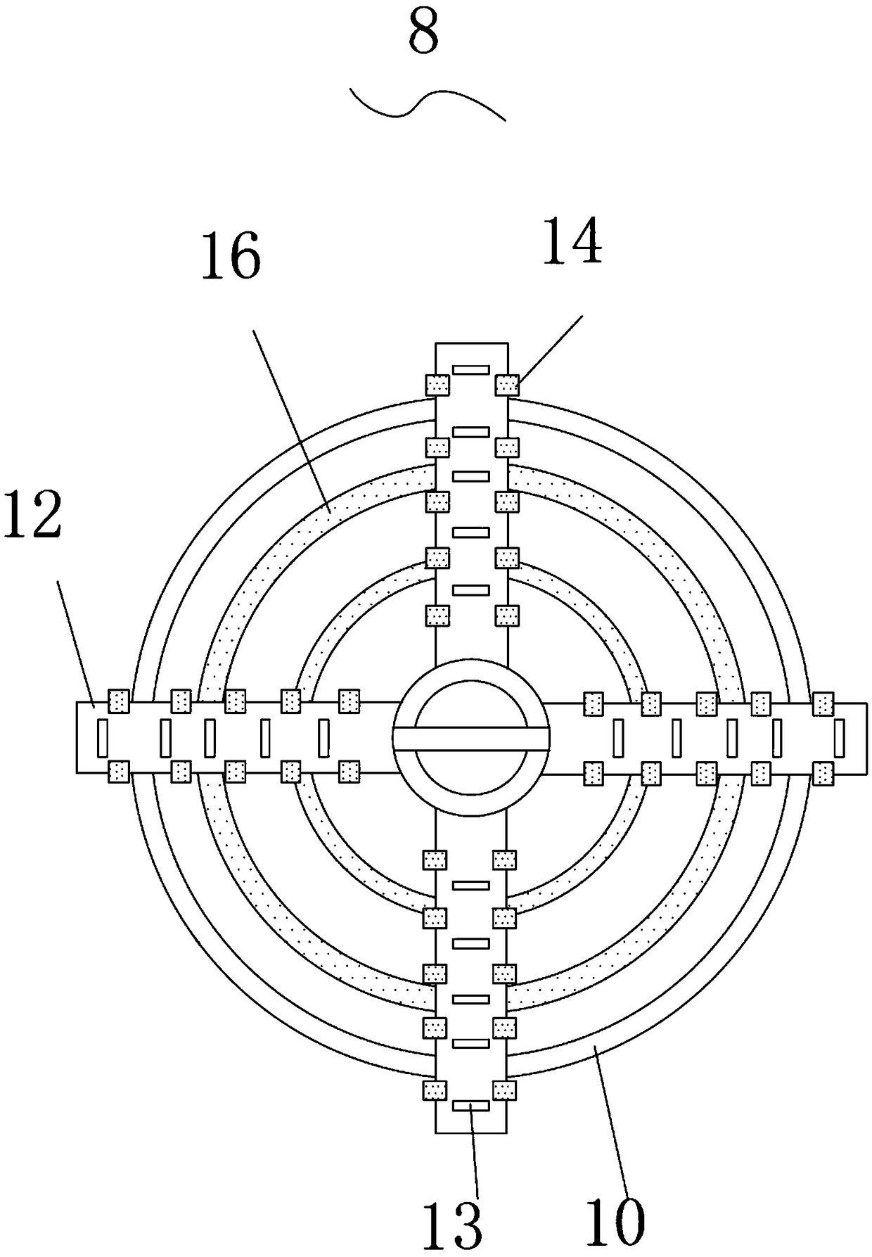
[0021] see Figure 1-6 , the present invention provides a technical solution: a combined cutter head of a rectangular pipe jacking machine, including a rectangular cylinder 1, and the outer edge of the excavation surface of the rectangular cylinder 1 is equipped with a "rectangular" peripheral guardrail 2 , the front side edge of the outer peripheral guardrail 2 is equidistantly welded with peripheral knives 3, through the setting of the peripheral knives 3, t...


PUM


Abstract

The invention discloses a combined cutterhead of a rectangular top pipe heading machine. The combined cutterhead comprises a rectangular cylinder. The outer edge of an excavation surface of the rectangular cylinder is provided with a peripheral guardrail which is arranged in a rectangular manner. Peripheral cutters are equidistantly welded at the front edge position of the peripheral guardrail. One circle of the excavation surface of the rectangular cylinder is provided with reinforcing blocks which are equidistantly welded on one circle of the excavation surface of the rectangular cylinder and are integrally formed with the inner wall of the peripheral guardrail. The middle part of the excavation surface and four hanging corners of the rectangular cylinder are respectively provided with amain installing hole and auxiliary installing holes. Through the combined design of the main cutterhead assembly and the auxiliary cutterhead assembly, an excavation area and excavation strength canbe enlarged; a main cutterhead assembly and an auxiliary cutterhead assembly have the same structure and respectively comprise a wheel hub and outer protecting ring; the axial position of the wheel hub is provided with a fish tail cutterhead; and through the fish tail cutterhead which projects in an axial direction, preliminary fragmentation excavation in a tunneling process of a pipe pushing jackcan be realized; and a pressure which is generated in a tunneling process can be shared through arranging a plurality of web plates.

Description

technical field [0001] The invention relates to the technical field of the cutter head of a pipe jacking machine, in particular to a combined cutter head of a rectangular pipe jacking machine. Background technique [0002] Rectangular pipe jacking machine is an effective tool for excavating pipelines and tunnels through underground excavation construction methods, and the cutter head is the primary tool for pipe jacking machine to fully excavate pipelines, but in the prior art more is used A single cutter head has low excavation efficiency, and the combined cutter head on the market has insufficient support strength, which is very easy to cause the spokes (that is, spokes) to break during the excavation process. At the same time, the outer peripheral guardrail of the excavation surface of the rectangular cylinder lacks support. The structure is easily deformed so that the peripheral knife on the front side is deformed, thereby enhancing the propulsion resistance of the excav...

Claims


Application Information

Patent Timeline
IPC IPC(8): E21D9/10
CPCE21D9/1006
Inventor 甘红兵
Owner 淮南中泰矿山装备制造有限公司
Learn More