
Detachable fabricated steel structure closed section column-column connecting node

A technology for connecting nodes and steel structures, applied in the direction of columns, pier columns, pillars, etc., can solve the problems of affecting the mechanical performance of nodes, increasing the cross-sectional area, affecting the construction speed and quality, and achieving the effect of improving assembly speed and quality

Inactive Publication Date: 2018-12-18
TSINGHUA UNIV +1
View PDF5 Cites 7 Cited by
  • Summary
  • Abstract
  • Description
  • Claims
  • Application Information

AI Technical Summary

Problems solved by technology

The column-column joints used in previous engineering examples have the following disadvantages: the upper and lower columns are connected by butt welds in commonly used steel column full-welded joints. This connection method has relatively poor ductility and requires on-site welding, which greatly affects construction speed and quality, at the same time, due to the large welding area, it is easy to generate large residual stress, which affects the mechanical performance of the joint; in the commonly used steel column high-strength bolt connection joints, flange plates with bolt holes are welded at the ends of the upper and lower columns, and then Connection by high-strength bolts
This connection method will significantly increase the cross-sectional area locally, occupy a large space, and is not beautiful

Method used


Image

  • Detachable fabricated steel structure closed section column-column connecting node
  • Detachable fabricated steel structure closed section column-column connecting node
  • Detachable fabricated steel structure closed section column-column connecting node

Examples


Embodiment Construction

[0022] In order to make the objectives, technical solutions and advantages of the present invention clearer, the technical solutions in the embodiments of the present invention will be described in more detail below in conjunction with the drawings in the embodiments of the present invention. In the drawings, the same or similar reference numerals denote the same or similar elements or elements having the same or similar functions throughout. The described embodiments are some, but not all, embodiments of the invention. The embodiments and directional words described below by referring to the figures are exemplary and are intended to explain the present invention, but should not be construed as limiting the present invention. Based on the embodiments of the present invention, all other embodiments obtained by persons of ordinary skill in the art without creative efforts fall within the protection scope of the present invention. Embodiments of the present invention will be des...


PUM


Abstract

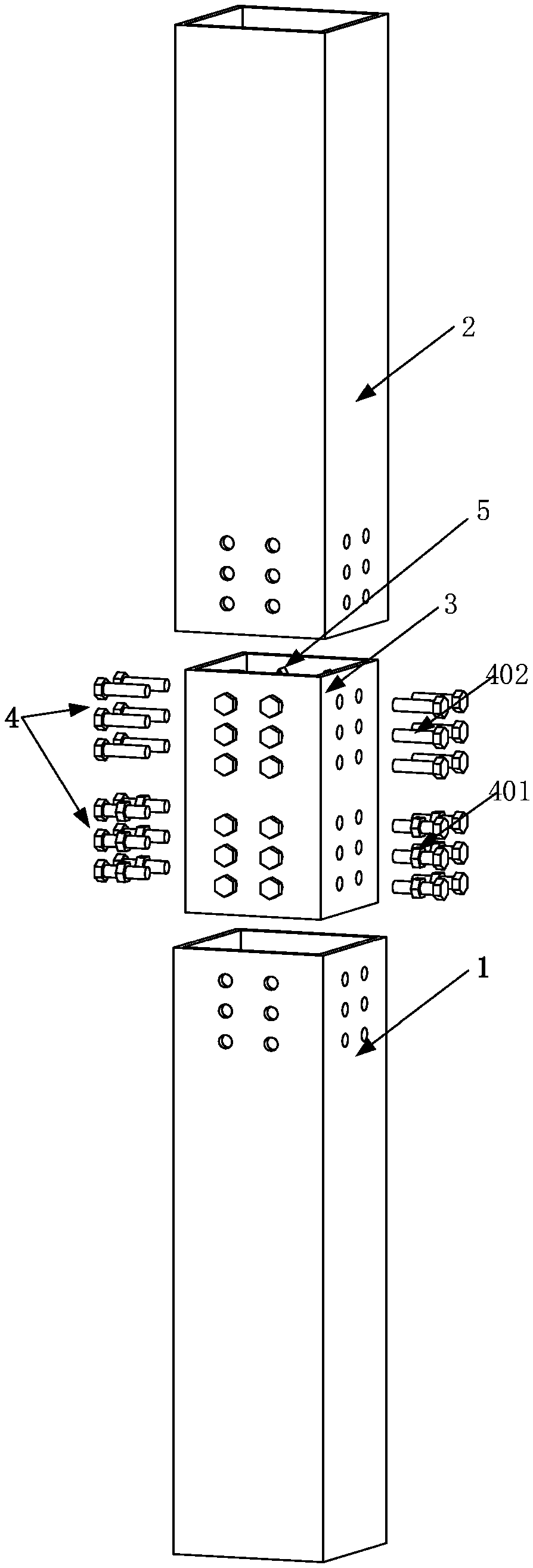
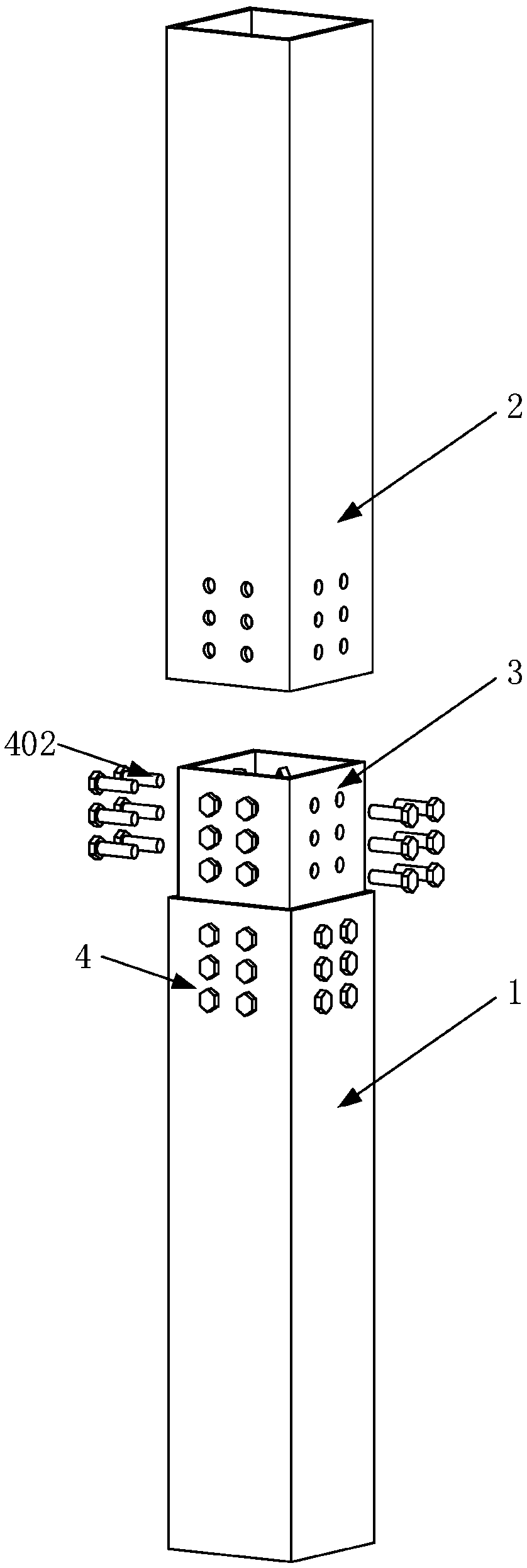
The invention relates to a detachable fabricated steel structure closed section column-column connecting node. The column-column connecting node comprises a lower column, an upper column, a sleeve andhigh-strength bolts. Bolt holes are reserved in the sleeve and the steel columns, and a nut is fixed by a special fixing device at the bolt hole reserved at the inner side of one end of the sleeve. When the connecting node is assembled, the sleeve and the lower column are connected and fixed by the traditional high-strength bolts, then the upper column sleeves the upper part of the sleeve, the reserved bolt holes of the sleeve are aligned with the reserved bolt holes of the upper column, then bolt rods traverse the reserved bolt holes from the outer side of the column, and the nuts pre-arranged in the inner side of the sleeve are unilaterally screwed in to realize the fastening of the upper column and the sleeve. When the service life expires and the connecting node is dismounted, the bolt rods are screwed off to separate the upper column and the sleeve. The steel structure closed section column-column connecting node has the advantages of high rigidity, insignificant increase of thesection area of a node area, simplicity in assembling and constructing, convenience in restoration after earthquake and replacement of damaged members, and convenience in dismounting of the structureafter the expiry of the service life.

Description

technical field [0001] The invention belongs to the technical field of structural engineering steel structures, and in particular relates to a detachable and assembled closed-section column-to-column connection node form of a closed section steel structure applied to industrial and civil building structural systems. Background technique [0002] The prefabricated steel structure system is a building produced by building units or components manufactured according to uniform and standard building part specifications, which are prefabricated in the factory and then transported to the construction site for assembly. The steel structure has good mechanical processing performance and is easy to assemble. The assembled building has the advantages of light weight and high strength, energy saving and environmental protection, fast construction speed, and high degree of industrialization. The development of industrialized prefabricated steel structure system is an urgent requirement o...

Claims


Application Information

Patent Timeline
Patent Type & Authority Applications(China)
IPC IPC(8): E04C3/32E04B1/343
CPCE04B1/343E04C3/32
Inventor 杨璐范俊伟班慧勇王元清
Owner TSINGHUA UNIV
Learn More