A water conservancy project pipeline dredging device and a special pipeline for dredging
A technology for water conservancy projects and desilting devices, applied in water supply devices, waterway systems, buildings, etc., can solve problems such as pipeline silt accumulation and blockage, and achieve the effects of small equipment size, manpower saving, and high reliability
- Summary
- Abstract
- Description
- Claims
- Application Information
AI Technical Summary
Problems solved by technology
Method used
Image
Examples
specific Embodiment approach 1
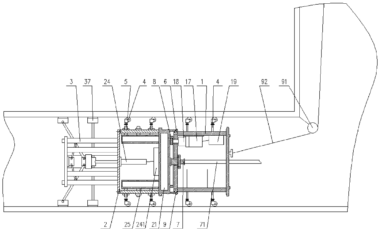
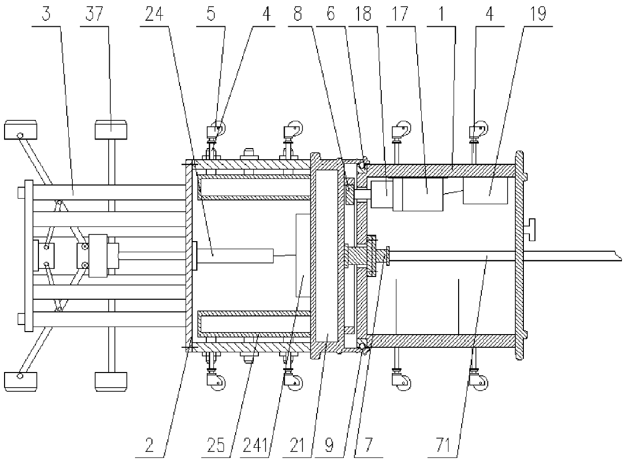
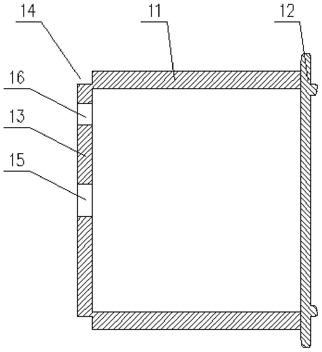
[0036] Specific implementation mode one: combine figure 1 with Figure 7Describe this embodiment, a water conservancy project pipeline dredging device in this embodiment, including a driving base 1, a pipeline sludge flushing device 2 and a pipeline washing device 3, the overall shape of the driving base 1 is cylindrical, and the outer wall of the driving base A support rod 4 is installed on the support rod 4, and a traveling wheel 5 is installed on the supporting rod 4. The traveling wheel 5 is a universal traveling wheel, and the driving base 1 includes a base housing 11 and a bottom cover 12. The base housing 11 has a The right end is an open structure, and a bottom cover 12 is installed on the right end of the base shell 11. An annular groove 14 is processed on the left side wall 13 of the base of the base shell 11, and an annular slide rail is installed in the annular groove 14. 6. The center position of the left side wall 13 of the base shell 11 is processed with a rota...
specific Embodiment approach 2
[0038] Specific implementation mode two: combination figure 1 with Figure 7 Describe this embodiment, a water conservancy project pipeline desilting device in this embodiment, the pipeline sludge flushing device 2 includes a water storage box 21, a flushing installation box 22, a flushing installation box cover 23, an electric push rod 24, Flushing pipe 25 and flushing head 26, the right side of described water storage box 21 is provided with slide block 9 and ring gear 10 respectively, and water storage box 21 is installed in the center position of pedestal left side wall 13 of the rotating rotary The joint 7 is connected, and the left side of the water storage box 21 is connected with a plurality of flushing pipes 25. The flushing installation box 22 is welded and installed on the left side of the water storage box 21. The flushing pipes 25 are arranged in the flushing installation box. 22, a flushing head 26 is installed on the flushing pipe 25, and the flushing head 26 e...
specific Embodiment approach 3
[0040] Specific implementation mode three: combination figure 1 with Figure 7 Describe this embodiment, a water conservancy project pipeline desilting device of this embodiment, the right side of the water storage box 21 has a water inlet 211, and the rotation of the water inlet 211 and the center position of the left side wall 13 of the base The adapter 7 is connected, and the left side of the water storage box 21 has water outlets 212 in an annular array, and each water outlet 212 is sealed with a flushing pipe 25 . In this way, the water inlet 211 is used to communicate with the rotary adapter 7 , and the water outlet 212 is communicated with the flushing pipe 25 .
PUM
 Abstract
Description
Claims
Application Information
 - Generate Ideas
- Intellectual Property
- Life Sciences
- Materials
- Tech Scout
- Unparalleled Data Quality
- Higher Quality Content
- 60% Fewer Hallucinations
Browse by: Latest US Patents, China's latest patents, Technical Efficacy Thesaurus, Application Domain, Technology Topic, Popular Technical Reports.
© 2025 PatSnap. All rights reserved.Legal|Privacy policy|Modern Slavery Act Transparency Statement|Sitemap|About US| Contact US: help@patsnap.com


