
Modulus type seamless telescopic device and a construction method thereof

A technology of seamless expansion and modulus, applied in bridge parts, bridges, buildings, etc., can solve the problems of easy aging of sealing rubber belts, insufficient bending rigidity, hidden safety hazards, etc., to improve driving comfort, easy installation and setting, The effect of low input cost

Active Publication Date: 2018-12-18
CHANGAN UNIV
View PDF7 Cites 8 Cited by
  • Summary
  • Abstract
  • Description
  • Claims
  • Application Information

AI Technical Summary

Problems solved by technology

However, there are some common problems in the conventional digital expansion joint device: noise is easily generated when vehicles pass by; the sealing rubber belt is easy to age and cause water leakage, and dust and other garbage are easy to accumulate in it, which hinders the normal deformation of the expansion device, etc.
[0004] There are some common problems in conventional comb-tooth plate telescopic devices: the middle part of the movable comb-tooth plate is deflected due to its own insufficient rigidity; in addition, the rotational displacement of the beam body or the end of the abutment will cause the comb teeth at the end of the movable comb-tooth plate to warp, giving The driving of the vehicle brings safety hazards. At the same time, the comb teeth will break after the vehicle is repeatedly rolled; dust and other garbage are easy to fill the bottom plate of the comb teeth, etc.
[0005] Conventional seamless expansion devices generally have some problems: the range of applicable bridge expansion is limited; under various loads, the middle part appears deflection due to insufficient bending stiffness, which affects driving comfort, etc.

Method used


Image

  • Modulus type seamless telescopic device and a construction method thereof
  • Modulus type seamless telescopic device and a construction method thereof
  • Modulus type seamless telescopic device and a construction method thereof

Examples


Embodiment Construction

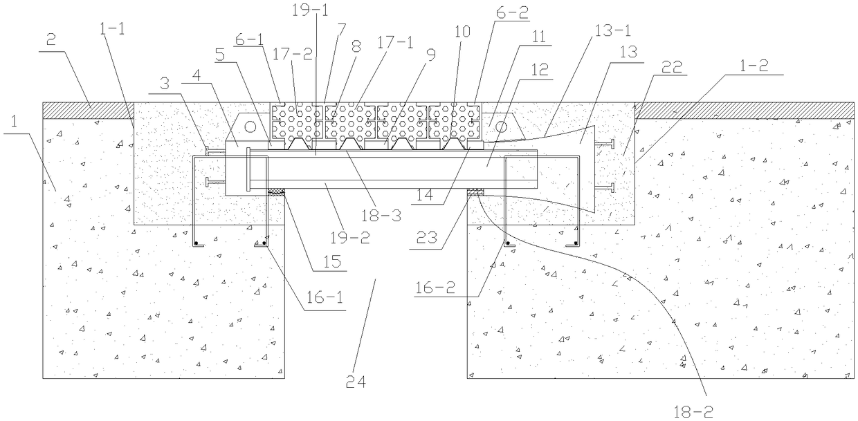
[0081] Such as figure 1 A modular seamless telescopic device shown includes a modular seamless telescopic device arranged on bridge expansion joints 24 formed by two adjacent girders or abutments 1, the modular seamless telescopic device The device includes a supporting mechanism installed in two girder bodies or abutments 1 and spanning the expansion joint 24 of the bridge, and a telescopic mechanism installed on the supporting mechanism. The telescopic mechanism includes a corrugated thin steel plate 10 and a corrugated thin steel plate 10, the telescopic deformation assembly includes two side beams symmetrically installed on both sides of the bridge expansion joint 24, a plurality of middle beams 7 arranged between the two side beams and connecting the side beams The elasto-plastic telescopic mechanism with the middle beam 7, the side beams are respectively the first side beam 6-1 and the second side beam 6-2, and the lower end of the first side beam 6-1 is provided with a ...


PUM


Abstract

The invention discloses a modulus type seamless expansion and contraction device and a construction method thereof, the device comprises a support mechanism and a telescopic mechanism, the telescopicmechanism comprises a corrugated steel sheet and a telescopic deformation assembly, the telescopic deformation assembly includes a side beam, a middle cross member and an elastoplastic expansion and contraction mechanism connecting the side cross member and the middle cross member, The lower end of the first side cross beam is provided with a fixed rubber damper, the lower end of the second side cross beam is provided with a fixed bearing damper, the lower end of the middle cross beam is provided with a sliding rubber damper, and the support mechanism comprises a first displacement box, a second displacement box, a support longitudinal beam, an upper U-shaped thin slide plate and a lower U-shaped thin slide plate; The method comprises the following steps: 1, mounting a support mechanism; 2. Installation of telescopic mechanism. The invention has the advantages of reasonable design, safer and more comfortable vehicle passing through the bridge expansion joint under the condition of satisfying the deformation of the bridge structure, and strong practicability.

Description

technical field [0001] The invention belongs to the technical field of bridge expansion devices, in particular to a modular seamless expansion device and a construction method thereof. Background technique [0002] Bridge expansion joints are one of the important components of bridge structure design. They are designed to meet the needs of expansion and deformation of beams and bridge decks caused by temperature changes, concrete shrinkage and creep, and various loads. A device for driving across a bridge deck. It is the weakest part of the bridge structure. It directly bears the impact of vehicle load and is exposed to the air for a long time. Therefore, it is easy to be damaged and the maintenance cost is high. If it is damaged and not maintained in time, it will affect the operation and safety of normal traffic. [0003] At present, according to JT T 327-2016 "General Technical Conditions for Highway and Bridge Expansion Devices", commonly used expansion devices are basi...

Claims


Application Information

Patent Timeline
Patent Type & Authority Applications(China)
IPC IPC(8): E01D19/06
CPCE01D19/062
Inventor 张岗万豪冯玉良王立志曹琳琳张晓威
Owner CHANGAN UNIV
Learn More