
Novel continuous charging device used for single crystal furnace

A technology of feeding device and single crystal furnace, applied in the direction of single crystal growth, single crystal growth, polycrystalline material growth, etc., can solve the problems of uneven distribution of silicon liquid crystal phase, difficulty in producing crystal rods, poor consistency of silicon liquid, etc. It is easy to promote, less investment, and the effect of reducing feeding

Pending Publication Date: 2018-12-18
宁夏旭樱新能源科技有限公司
View PDF0 Cites 3 Cited by
  • Summary
  • Abstract
  • Description
  • Claims
  • Application Information

AI Technical Summary

Problems solved by technology

[0002] At present, the charging of single crystal furnace is basically to place the silicon material in the quartz crucible in advance, and when placing the silicon material, the small piece of silicon material should be placed at the bottom of the quartz crucible, and the largest piece of silicon material should be placed in the quartz crucible Place the medium-sized silicon material in the quartz crucible on the top of the quartz crucible. There are other similar placement methods for the silicon material. When the silicon material does not meet the process requirements, it will often cause silicon liquid crystal phase Uneven distribution and poor consistency of silicon liquid will adversely affect the crystal pulling process, such as causing the crystal pulling time to be too long, the quality of the crystal rod is not good, and it is difficult to produce crystal rods with high purity and good crystal phase consistency

Method used


Image

  • Novel continuous charging device used for single crystal furnace
  • Novel continuous charging device used for single crystal furnace
  • Novel continuous charging device used for single crystal furnace

Examples


Embodiment Construction

[0024] In order to more clearly illustrate the technical solutions of the embodiments of the present invention, the following will briefly introduce the accompanying drawings that need to be used in the embodiments. Obviously, the accompanying drawings in the following description are some embodiments of the present invention. Ordinary technicians can also obtain other drawings based on these drawings without paying creative work.

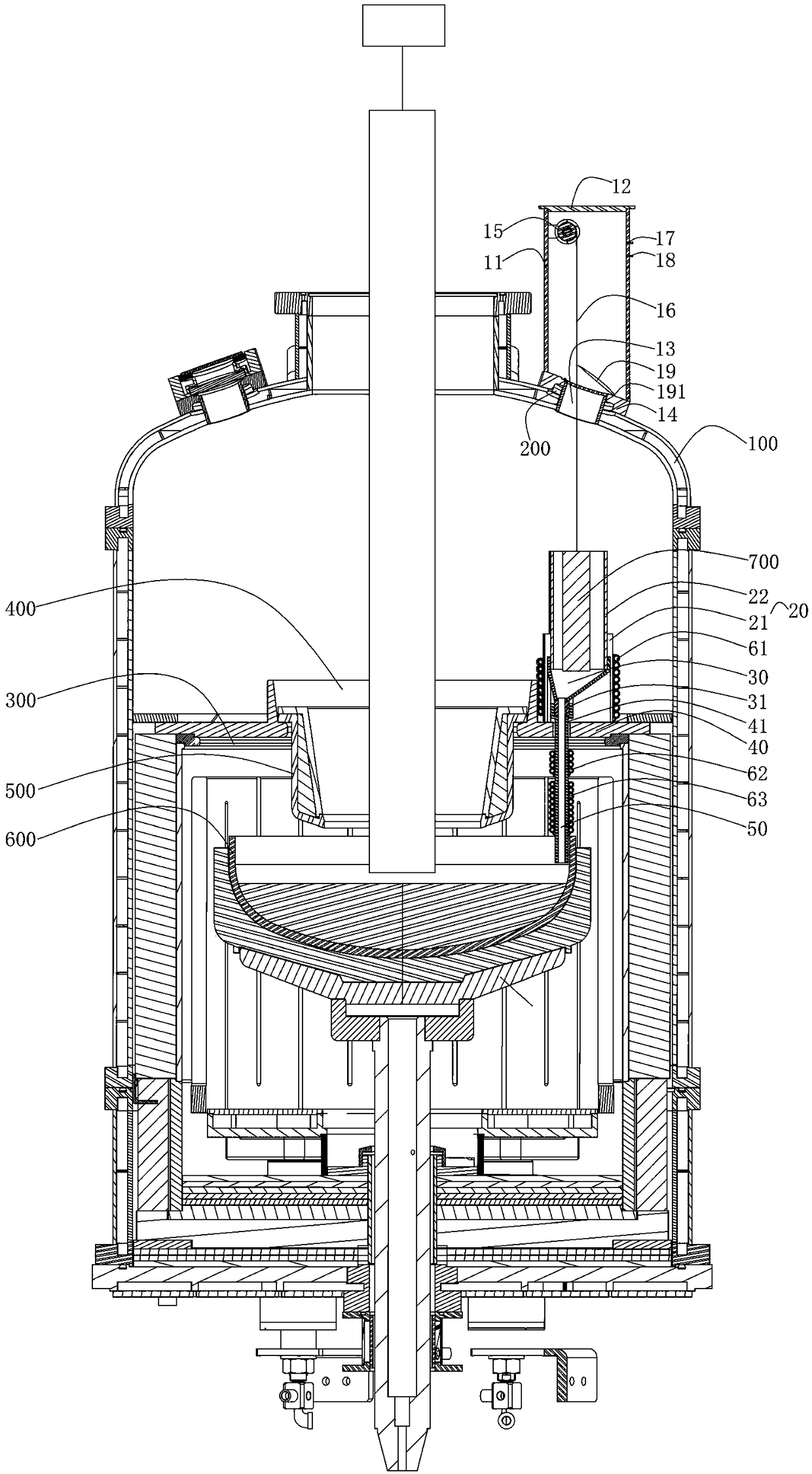
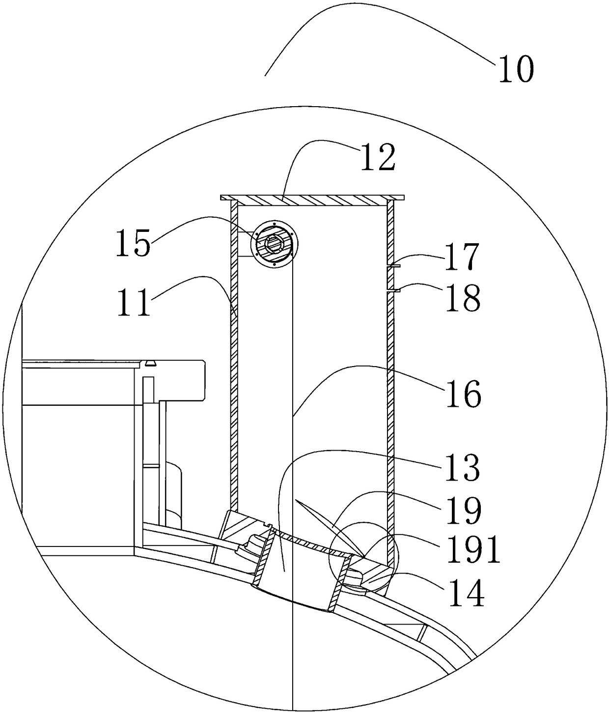
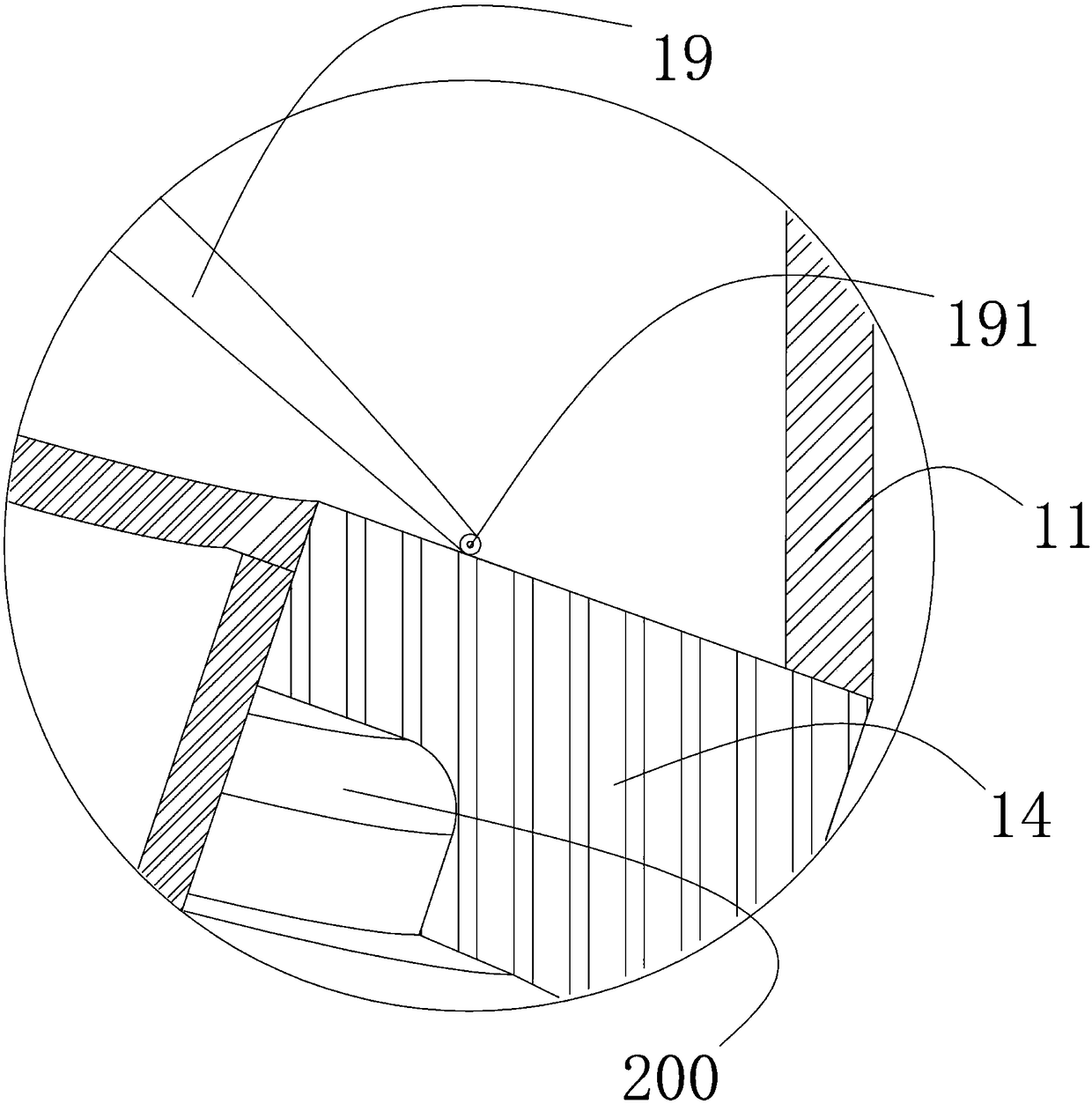
[0025] see Figure 1 to Figure 4 , the present invention provides a novel continuous feeding device for a single crystal furnace, including a storage device 20, a transition device 30, a fixing device 40, a liquid outlet device 50, and a heating device 60, and the storage device 20 is arranged on a furnace body 100 The lower end of the transition device 30 is connected to the storage device 20, the transition device 30 is arranged on the upper end of the fixing device 40, the transition device 30 is a funnel-shaped cavity, and the transition device...


PUM


Abstract

The invention a novel continuous charging device used for a single crystal furnace. The novel continuous charging device used for the single crystal furnace comprises a material storage device, a transition device, a fixing device, a liquid exporting device and a heating device and also comprises a batch charging device, wherein the batch charging device is arranged on the upper end of a furnace body; the just lower end of the batch charging device is provided with a material storage device; the material storage device is arranged on the lower end of the furnace body; the inlet end of the transition device is connected with the material storage device; the transition device is arranged on the upper end of the fixing device; the inlet end of the liquid exporting device is connected with theoutlet end of the transition device; the outlet end of the liquid exporting device is arranged on the inner wall of a quartz crucible; the heating device surrounds the outer sides of the transition device and the liquid exporting device. By use of the novel continuous charging device, the problems in the prior art that silicon liquid crystal phase distribution is uneven and silicon liquid consistency is poor after silicon materials are fused are thoroughly solved, pre-charging is not required, charging and material melting time is shortened, silicon rod fusion efficiency and levels are improved, crystal pulling efficiency is improved, labor intensity and production cost are effectively lowered, and meanwhile, the novel continuous charging device is convenient for popularization since input is low.

Description

technical field [0001] The invention relates to the field of single-polycrystal technology, in particular to a novel continuous feeding device for a single-crystal furnace. Background technique [0002] At present, the charging of single crystal furnace is basically to place the silicon material in the quartz crucible in advance, and when placing the silicon material, the small piece of silicon material should be placed at the bottom of the quartz crucible, and the largest piece of silicon material should be placed in the quartz crucible Place the medium-sized silicon material in the quartz crucible on the top of the quartz crucible. There are other similar placement methods for the silicon material. When the silicon material does not meet the process requirements, it will often cause silicon liquid crystal phase Uneven distribution and poor consistency of the silicon liquid will adversely affect the crystal pulling process, such as causing the crystal pulling time to be too...

Claims


Application Information

Patent Timeline
IPC IPC(8): C30B15/02C30B15/14C30B29/06
CPCC30B15/002C30B15/02C30B15/14C30B29/06
Inventor 张建新
Owner 宁夏旭樱新能源科技有限公司
Learn More