Equipment loading and unloading tool, equipment assembling method and equipment disassembling method

A technology for loading and unloading workers and equipment, which is applied to manufacturing tools, workpiece clamping devices, hand-held tools, etc., and can solve the problems of difficult to ensure the coaxiality of the impeller and the volute, difficult to grasp the overall axial size, and difficult to match the angle. , to achieve the effect of solving the problem of disassembly, high efficiency and high assembly accuracy

Active Publication Date: 2018-12-18
TECHNICAL INST OF PHYSICS & CHEMISTRY - CHINESE ACAD OF SCI
View PDF4 Cites 4 Cited by
  • Summary
  • Abstract
  • Description
  • Claims
  • Application Information

AI Technical Summary

Problems solved by technology

The traditional integrated loading and unloading process of low-temperature rotating machinery on the flange of the cold box is usually an assembly scheme with a gantry crane and manual alignment. Therefore, it is difficult to grasp the overall axial dimension during the manual loading and unloading process, and it is difficult to ensure the matching of the angle during the assembly process. It is difficult to guarantee the coaxiality requirement with the volute, and it is easy to produce assembly errors

Method used


Image

  • Equipment loading and unloading tool, equipment assembling method and equipment disassembling method
  • Equipment loading and unloading tool, equipment assembling method and equipment disassembling method
  • Equipment loading and unloading tool, equipment assembling method and equipment disassembling method

Examples


Embodiment Construction

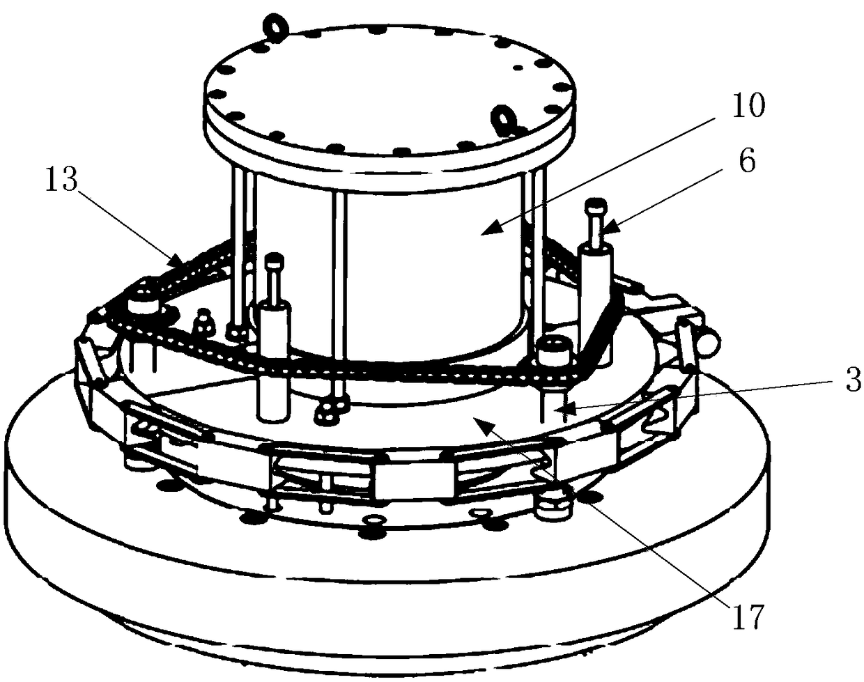
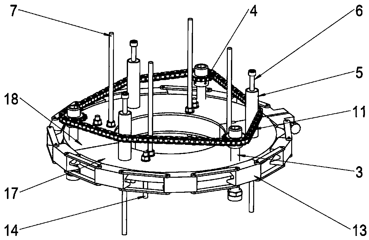
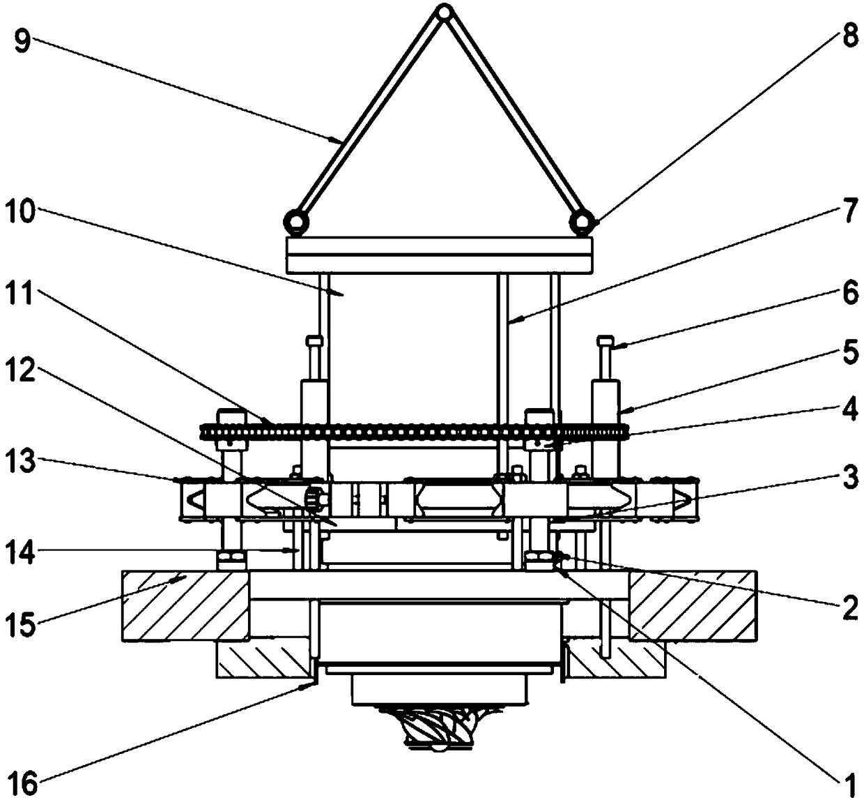
[0036] In order to make the purpose, technical solution and advantages of the present invention clearer, the present invention will be further described in detail below in conjunction with the accompanying drawings and embodiments. It should be understood that the specific embodiments described here are only used to explain the present invention, not to limit the present invention.

[0037] For the overall efficiency of the low-temperature rotating machinery design process, three aspects need to be considered: firstly, considering the particularity of the helium working medium itself (small molecules, high adiabatic index), it is necessary to increase the working speed as much as possible while considering the limitation of the low-temperature strength of the impeller to optimize To the optimal flow coefficient, the circumferential speed of the impeller is often ≥ 200m / s after the optimized design. Secondly, the material strength is limited during design, and the impeller size...


PUM


Abstract

The invention provides an equipment loading and unloading tool. The equipment loading and unloading tool comprises a clamping and fastening structure, an axial adjusting structure and a radial alignment structure; the clamping and fastening structure comprises an annular chuck and a fastener, the annular chuck comprises at least two arc-shaped tooling support blocks, the tool supporting blocks arespliced end to end to form an annular chuck, and the fastener is used for tightly fixing the annular chuck; the axial adjusting structure comprises supporting legs, the supporting legs penetrate through the annular chuck, and the supporting legs are in threaded connection with the annular chuck; and positioning rods penetrates through the annular chuck. According to the loading and unloading tool, to-be-installed low-temperature machinery is clamped by adopting the clamping and fastening structure. By rotating the supporting legs, the tool supporting blocks drive the to-be-installed equipmentto generate axial displacement, so that the installing and dismounting are realized. In the installation process of the equipment, the positioning rods are screwed into positioning holes of a flangeat the lower end, so that the radial positioning of the tool and the mechanical assembly can be realized, the coaxiality is improved, and the assembly error is reduced. In addition, the invention further provides an equipment assembling method and an equipment disassembling method adopting the equipment loading and unloading tool.

Description

technical field [0001] The invention relates to the technical field of loading and unloading tooling, in particular to a tooling for loading and unloading equipment, a method for assembling the equipment, and a method for disassembling the equipment. Background technique [0002] Large-scale helium cryogenic refrigeration equipment is an irreplaceable basic support for high-tech application fields such as aviation, nuclear science, and superconducting physics, and provides the required ultra-low temperature environment for the normal operation of large scientific systems. In order to meet the urgent needs of large-scale low-temperature refrigeration systems in the liquid helium to superfluid helium temperature zone of major national science and technology infrastructure construction projects (ADS and HIAF, etc.) and the status and needs of national strategic helium resources, it is urgent to develop a set of liquid helium to superfluid helium The large-scale low-temperature ...

Claims


Application Information

Patent Timeline
Patent Type & Authority Applications(China)
IPC IPC(8): B25B11/02B25B27/00
CPCB25B11/02B25B27/00Y02E30/30
Inventor 伍继浩董欣勃吕翠潘薇李青龚领会
Owner TECHNICAL INST OF PHYSICS & CHEMISTRY - CHINESE ACAD OF SCI
Why Eureka
Try Eureka