Edging device applicable to glass in various shapes and glass edging method
A technology of various shapes and glasses, which is applied in the direction of machine tools, grinding machines, grinding/polishing equipment, etc., which are suitable for grinding the edge of workpieces, and can solve the problems of difficult control of edging force and amount, glass breaking, and glass edging device Solve problems such as single use, achieve the effect of reducing the steps of turning and handling, improving the efficiency of edging, and reducing labor
- Summary
- Abstract
- Description
- Claims
- Application Information
AI Technical Summary
Problems solved by technology
Method used
Image
Examples
Embodiment 1
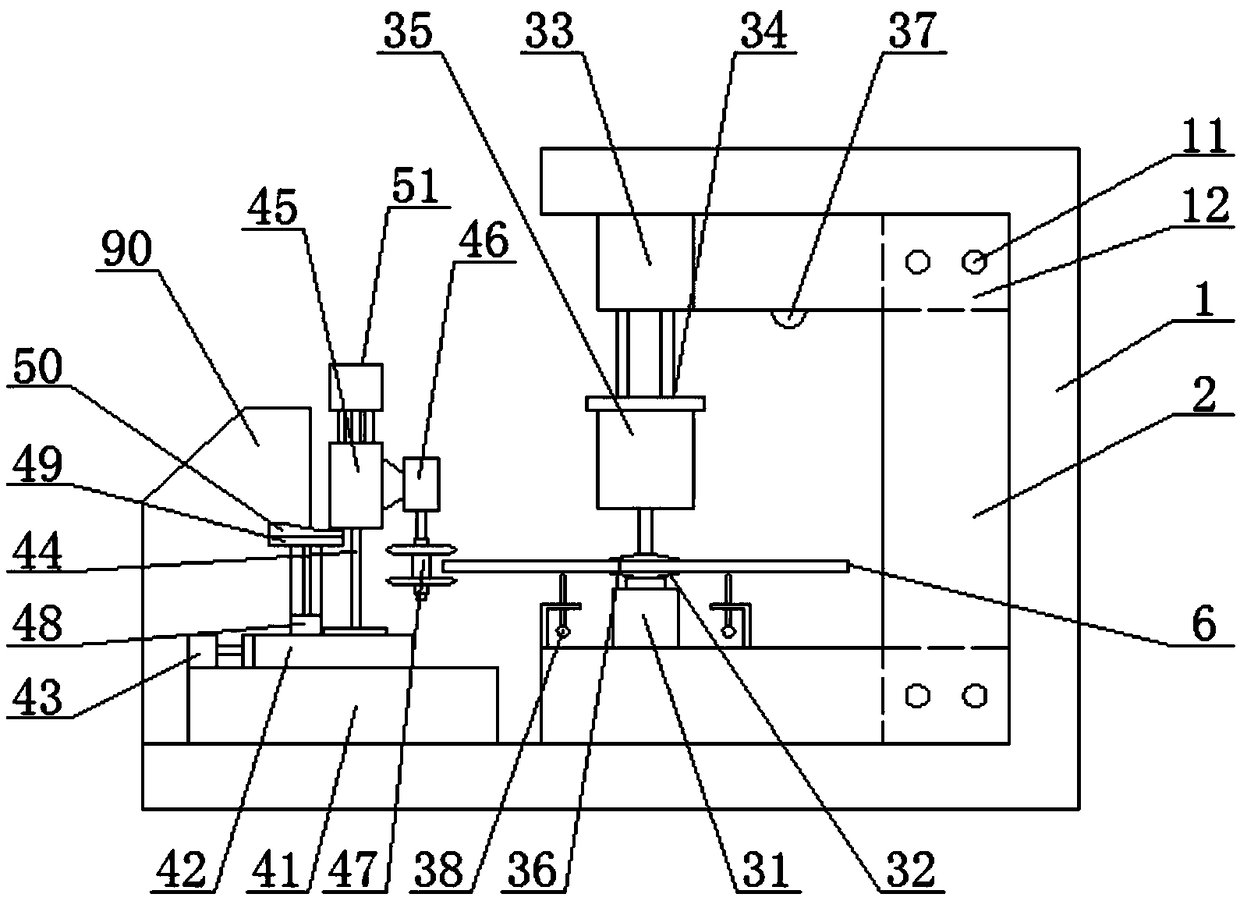
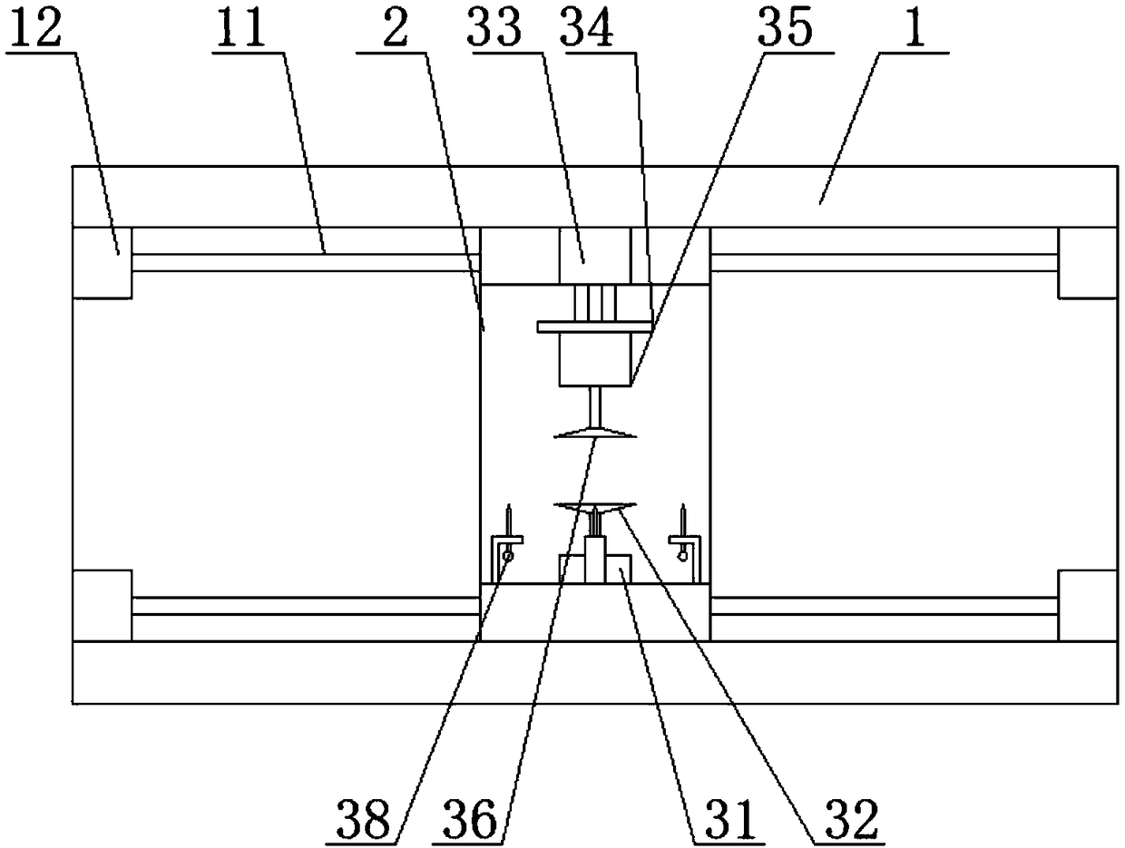
[0035] combined with figure 1 And attached figure 2 As shown, the present invention relates to an edging device applicable to various shapes of glass, which includes a cabinet, a clamping mechanism, an edging mechanism and a control system, and the cabinet includes an outer casing 1 and a mobile base 2, The inside of the outer casing 1 is provided with guide columns 11 arranged horizontally and corresponding up and down. The two ends of the guide columns 11 are provided with a base drive device 12. The base drive device 12 adopts an oil cylinder. The mobile base 2 is in a U-shaped structure. The seat 2 is arranged inside the outer casing 1 , the guide post 11 runs through the mobile base 2 , and the mobile base 2 is driven by the base driving device 12 so that it can move back and forth along the direction of the guide post 11 .
[0036]Described clamping mechanism comprises clamping cylinder 33, rotating disk 31 and rotating motor 35, and clamping cylinder 33 is fixed on th...
Embodiment 2
[0040] This embodiment is based on the attached Figure 6 The circular glass edging shown is taken as an example, and the edging method using the glass edging machine described in Embodiment 1 is described. The steps include,
[0041] Step 1: Attach the Figure 6 The shown glass 6 is placed on the turntable, and the glass 6 generates pressure to the surrounding measuring instruments 38, and the surrounding measuring instruments 38 send their respective pressure values to the main control machine 90 for analysis, and the display screen of the main control machine 90 displays each Measure the pressure value of the instrument 38, and adjust the position of the glass 6 according to the pressure difference, so that the center of gravity of the glass 6 falls on the axis of the turntable 31, and the clamping cylinder 33 is controlled by the main control machine 90 to press down the rotating motor 35, so that the rotating motor The upper sucker 36 of 35 lower ends and the upper su...
Embodiment 3
[0046] This embodiment is based on the attached Figure 7 The rectangular glass edging shown is taken as an example, and the edging method using the glass edging machine described in Embodiment 1 is described. The steps include,
[0047] Step 1: Attach the Figure 7 The shown glass 6 is placed on the turntable, and the glass 6 generates pressure to the surrounding measuring instruments 38, and the surrounding measuring instruments 38 send their respective pressure values to the main control machine 90 for analysis, and the display screen of the main control machine 90 displays each Measure the pressure value of the instrument 38, and adjust the position of the glass 6 according to the pressure difference, so that the center of gravity of the glass 6 falls on the axis of the turntable 31, and the clamping cylinder 33 is controlled by the main control machine 90 to press down the rotating motor 35, so that the rotating motor The upper sucker 36 of 35 lower ends and the upper...
PUM
 Abstract
Description
Claims
Application Information
 - R&D
- Intellectual Property
- Life Sciences
- Materials
- Tech Scout
- Unparalleled Data Quality
- Higher Quality Content
- 60% Fewer Hallucinations
Browse by: Latest US Patents, China's latest patents, Technical Efficacy Thesaurus, Application Domain, Technology Topic, Popular Technical Reports.
© 2025 PatSnap. All rights reserved.Legal|Privacy policy|Modern Slavery Act Transparency Statement|Sitemap|About US| Contact US: help@patsnap.com


