Treatment device for orthopedic spinal injury
A spinal injury and treatment device technology, applied in physical therapy, passive exercise equipment, vibration massage, etc., can solve the problems of inconvenient use, single function, high cost, etc., and achieve the effect of strong practicability and ingenious structure
- Summary
- Abstract
- Description
- Claims
- Application Information
AI Technical Summary
Problems solved by technology
Method used
Image
Examples
Embodiment 1
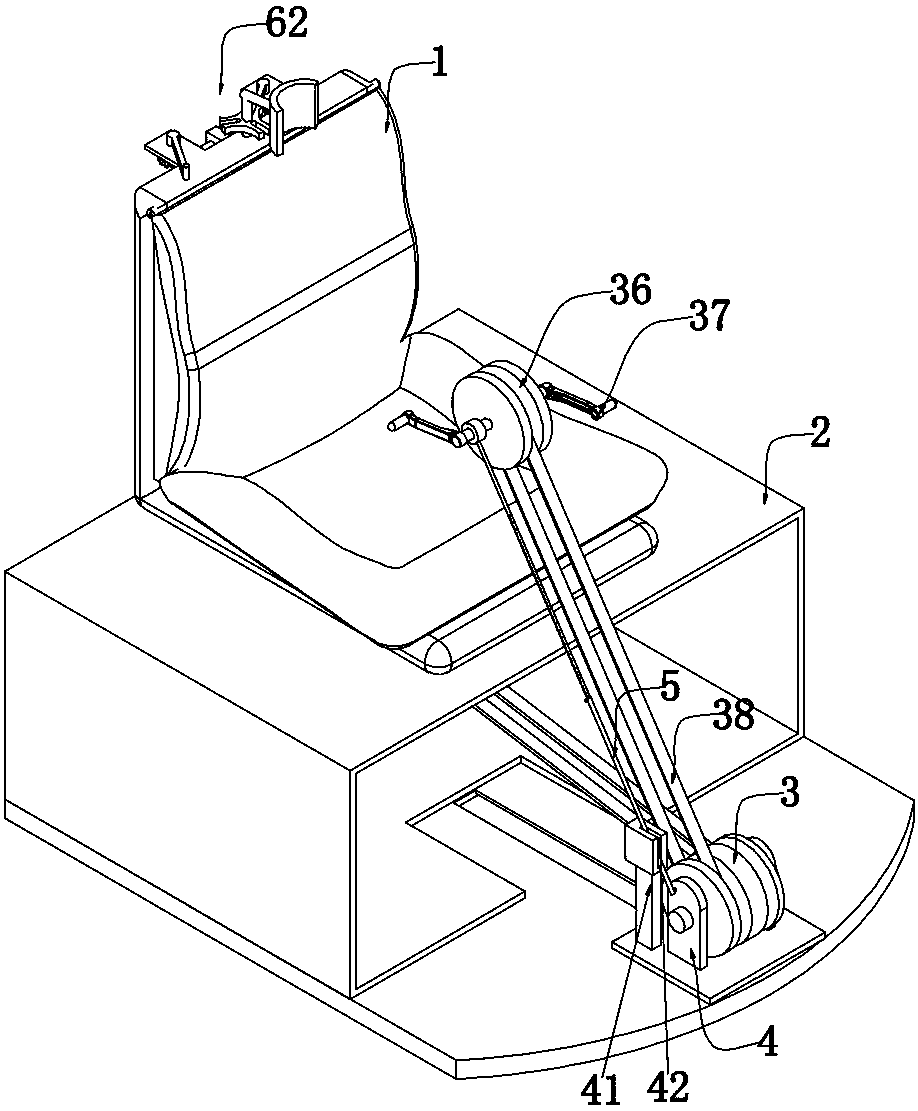
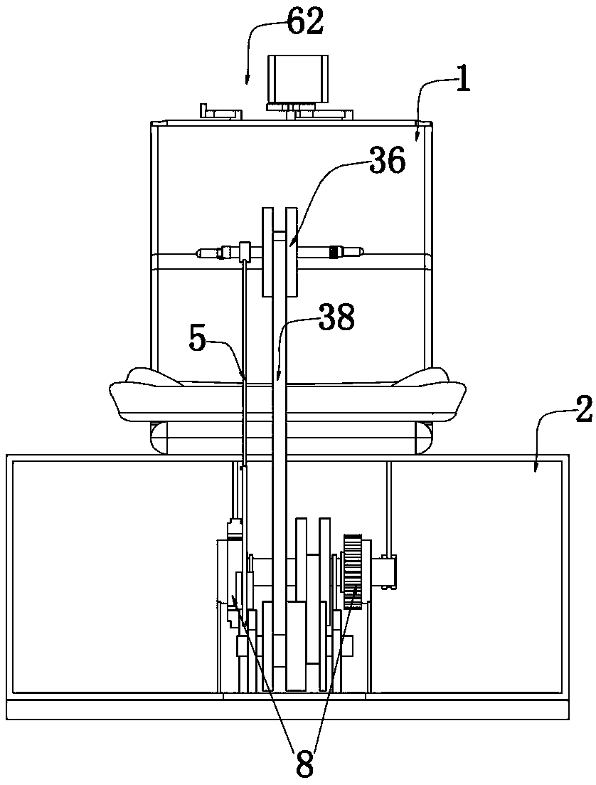
[0045] Embodiment 1, the present invention is an orthopedic spinal injury treatment device, please refer to figure 1 , including a seat base 1 and a hollow storage box 2 placed inside the lower end of the seat base 1, the front end of the seat base 1 is provided with a transfer pulley 3 that can slide in the front and rear directions, and the bearing wheel of the transfer pulley 3 A telescopic rod 5 is rotated on the seat 4, and the upper end of the telescopic rod 5 is rotated to be provided with a hand turntable 36. Both sides of the hand turntable 36 are equipped with rotating handles 37. The hand turntable 36 and the transfer pulley 3 pass through the main The transmission of the belt 38 is coordinated, and the driving pulley 39 provided with the internal rotation of the transfer pulley 3 and the storage box 2 is connected through the transmission of the auxiliary belt 40; Locking, so that when the hand turntable 36 is rotated to the front of the treatment personnel, the te...
Embodiment 2
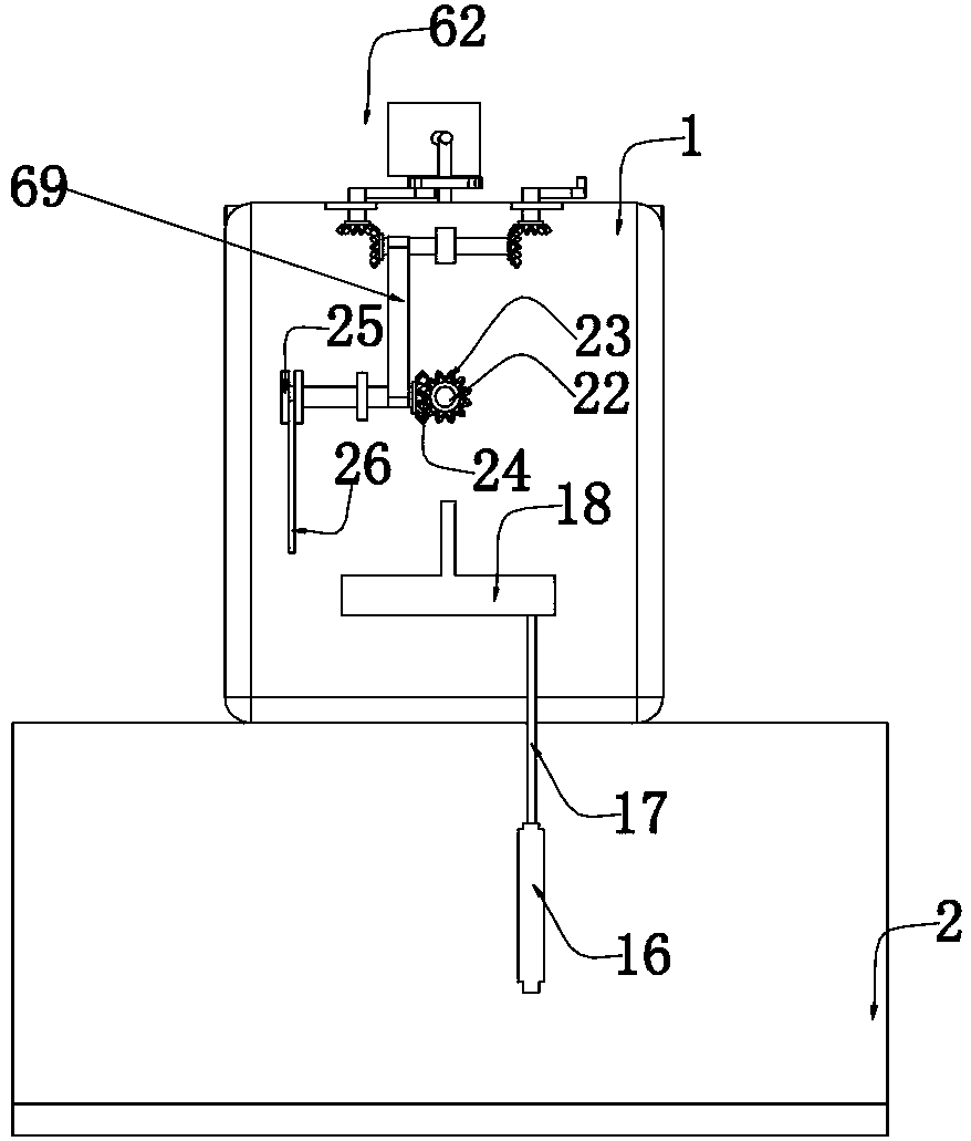
[0054] Embodiment two, on the basis of embodiment one, please refer to Image 6 with Figure 8 , the one-way wheel 8 includes a first flywheel 11 and a second flywheel 12, specifically, the outer rings of the first flywheel 11 and the second flywheel 12 are provided with axle seats fixed inside the storage box 2, and the first flywheel 11 and the inside of the second flywheel 12 are provided with opposite pawls, so that only one of the one-way wheels 8 rotates when the sprocket 6 rotates forward or reversely, see Image 6 , the outer ring of the first flywheel 11 is provided with incomplete teeth 13, the upper and lower ends of the first flywheel 11 are meshed with a rack 14, and the two racks 14 are fixedly connected by a rack connecting rod 15 at the end. Reciprocating rack 16, the reciprocating rack 16 is slidingly matched with the storage box 2 in the front and rear direction, please refer to Figure 7 , the upper end of the rack connecting rod 15 fixes the lumbar percus...
Embodiment 3
[0056] Embodiment three, on the basis of embodiment two, please refer to Figure 8 , the outer ring of the second flywheel 12 is meshed with a gear 20 that rotates with the storage box 2, and the gear 20 is coaxially fitted with a first pulley 21. Please refer to image 3 with Figure 8 , the back spine massage device 10 includes a rotating shaft 22 that is placed on the back of the seat base 1 and rotates, the rotating shaft 22 is fixed with a first bevel gear 23, and the first bevel gear 23 is meshed with a second bevel gear 24, The second bevel gear 24 is coaxially fixedly connected with a second pulley 25, and the second pulley 25 and the first pulley 21 are in transmission cooperation with the first pulley 21 through a belt 26. The front end of the rotating shaft 22 is fixed with a massage gear 27, and the massage gear 27 A number of massage sticks 28 are uniformly fixed on the front end;
[0057] When this embodiment is used in practice, when the treatment personnel ne...
PUM
 Abstract
Description
Claims
Application Information
 - R&D
- Intellectual Property
- Life Sciences
- Materials
- Tech Scout
- Unparalleled Data Quality
- Higher Quality Content
- 60% Fewer Hallucinations
Browse by: Latest US Patents, China's latest patents, Technical Efficacy Thesaurus, Application Domain, Technology Topic, Popular Technical Reports.
© 2025 PatSnap. All rights reserved.Legal|Privacy policy|Modern Slavery Act Transparency Statement|Sitemap|About US| Contact US: help@patsnap.com


