
Image compression method and electronic device

An image compression, grid technology, applied in image communication, image coding, image data processing and other directions

Active Publication Date: 2018-12-14
INST OF IND TECH GUANGZHOU & CHINESE ACADEMY OF SCI
View PDF6 Cites 0 Cited by
  • Summary
  • Abstract
  • Description
  • Claims
  • Application Information

AI Technical Summary

Problems solved by technology

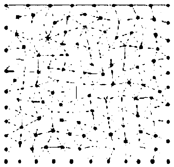
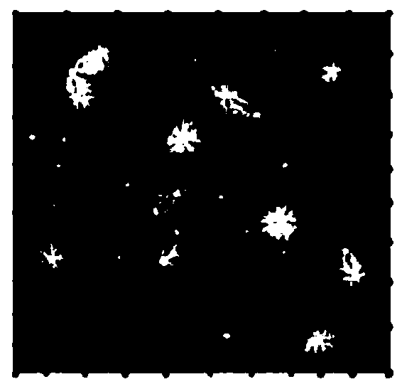
can be seen figure 1 The original image with image 3 Image restored from triangle mesh has large gaps

Method used


Image

  • Image compression method and electronic device
  • Image compression method and electronic device
  • Image compression method and electronic device

Examples


Embodiment Construction

[0064] The present invention will be described in further detail below in conjunction with the accompanying drawings and specific embodiments.

[0065] like Figure 4 Shown is the work flowchart of a kind of image compression method of the present invention, comprises:

[0066] Step S401, prepare an initial grid whose size is [0, X]×[0, Y] and contains N grid nodes, and set the color value of the pixel whose coordinates are (l, h) in the image whose size is L×H Stored in the grid at coordinates (x i the y i ) of the nth i grid nodes, where:

[0067] is the rounding symbol;

[0068] Step S402, generating an optimized adaptive anisotropic grid through adaptive anisotropic grid technology;

[0069] Step S403, restore the original image by spline linear interpolation, check whether the image pixel information stored in the optimized adaptive anisotropic grid meets the requirements, if not, use the optimized adaptive anisotropic grid grid as the new initial grid, and re...


PUM


Abstract

A method and electronic device for image compression are disclosed. The method includes: step A, for the initial grid, storing the color value (shown in the description) of the pixel with coordinates(l, h) in the image to the ni-th grid node with coordinates (xi, yi) in the grid; B, generating an optimized adaptive anisotropic mesh through an adaptive anisotropic mesh technology; Step C, restoring the original image by spline linear interpolation, checking whether the image pixel information stored in the optimized adaptive anisotropic mesh meets the requirements, if not, using the optimizedadaptive anisotropic mesh as a new initial mesh, and returning to step A for next iteration. The invention utilizes the characteristics of the finite element mesh in the computational mechanics and based on the adaptive anisotropic mesh optimization technology, is applied in the image compression technology, and greatly saves the storage space of the image. This technique is not only limited to two-dimensional image compression, but also extends to three-dimensional image compression applications.

Description

technical field [0001] The invention relates to the technical field of image processing, in particular to an image compression method and electronic equipment. Background technique [0002] With the continuous development of photography technology, images can capture very subtle details, especially in the medical field has made great contributions. However, the image size becomes larger and larger, contains a lot of pixels, consumes a large amount of image storage space, and is not easy for image transmission. Traditional image compression techniques include lossy compression and lossless compression, and these compression techniques are all implemented through data processing. [0003] Image information is composed of pixels, each pixel is in the shape of a small square and has a color value, and the pixels are arranged horizontally and vertically according to certain rules. The finite element grid is mainly used in computational mechanics, which provides a discrete conti...

Claims


Application Information

Patent Timeline
Patent Type & Authority Applications(China)
IPC IPC(8): H04N19/182H04N19/186G06T9/00
CPCG06T9/00H04N19/182H04N19/186
Inventor 赵佳欣尚菲菲丁桦
Owner INST OF IND TECH GUANGZHOU & CHINESE ACADEMY OF SCI
Learn More