A battery cell and cover plate assembly structure and assembly method thereof

An assembly structure and cover plate technology, which is applied in the direction of battery assembly, secondary battery manufacturing, sustainable manufacturing/processing, etc., can solve the problem of easily scratched diaphragm, achieve convenient operation, simple manufacturing process, and high utilization rate of raw materials Effect

Pending Publication Date: 2018-12-14
ETRUST POWER ETP GRP LTD
View PDF7 Cites 0 Cited by
  • Summary
  • Abstract
  • Description
  • Claims
  • Application Information

AI Technical Summary

Problems solved by technology

[0004] Purpose of the invention: In view of the above problems, the purpose of the present invention is to provide an assembly structure and assembly method of the battery cell and the cover plate, so as to solve the technical problem that the diaphragm is easily scratched

Method used


Image

  • A battery cell and cover plate assembly structure and assembly method thereof
  • A battery cell and cover plate assembly structure and assembly method thereof
  • A battery cell and cover plate assembly structure and assembly method thereof

Examples


Embodiment 1

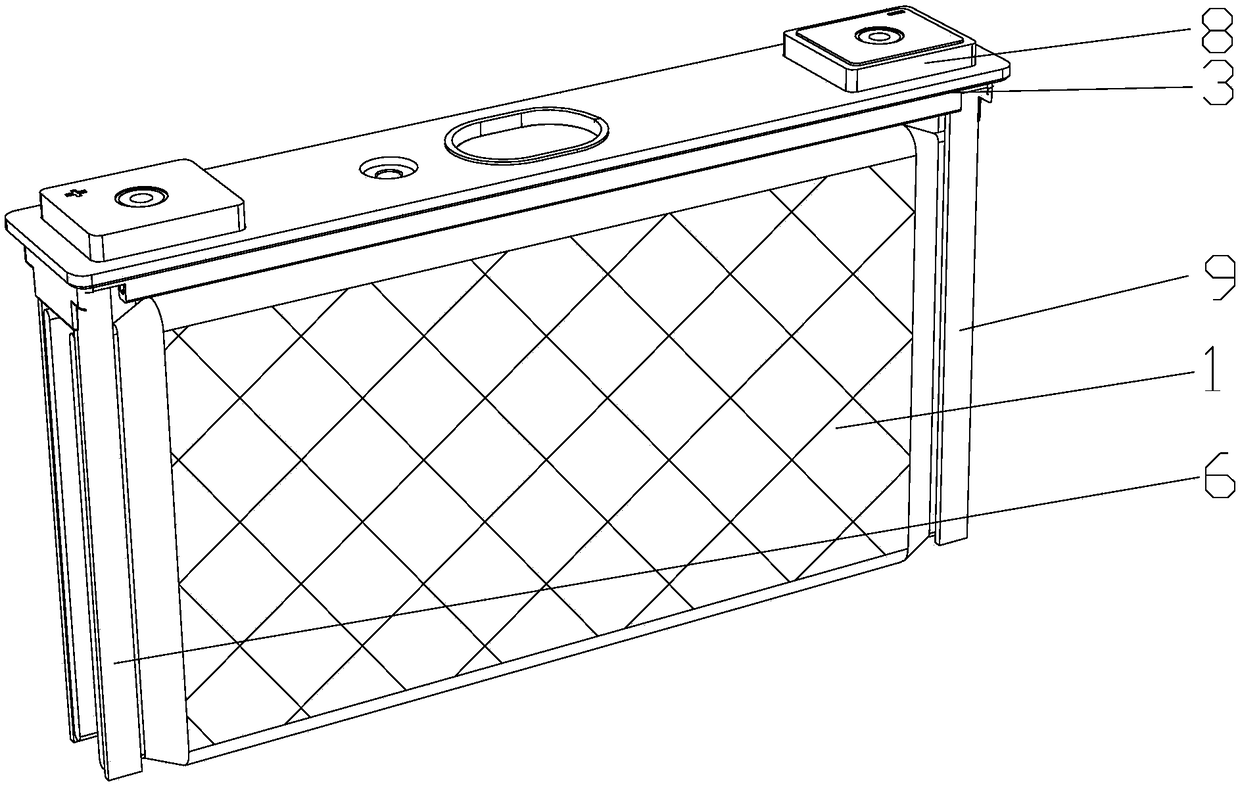
[0032] See figure 1 , 3 ~6, a battery cell and cover plate assembly structure, including two bare battery cells 1, a cover plate structure 2, and the cover plate structure 2 includes a top cover 3, a lower plastic 4, a positive conductive block 5, and a positive pole claw structure 6, Positive pole 7, negative electrode conductive block 8, negative electrode plastic 19, negative pole claw structure 9, negative pole 10, sealing ring 22, sealing ring two 23, positive electrode conductive block 5, negative electrode conductive block 8, and negative electrode plastic 19 are all installed On the upper surface of the top cover 3, the negative conductive block 8 is located in the negative upper plastic 19, the lower plastic 4 is located under the top cover 3, and the sealing ring 22 and the second sealing ring 23 are both located between the top cover 3 and the lower plastic 4. .

[0033] The positive pole claw structure 6 and the negative pole claw structure 9 are respectively located ...

Embodiment 2

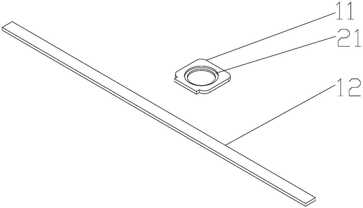
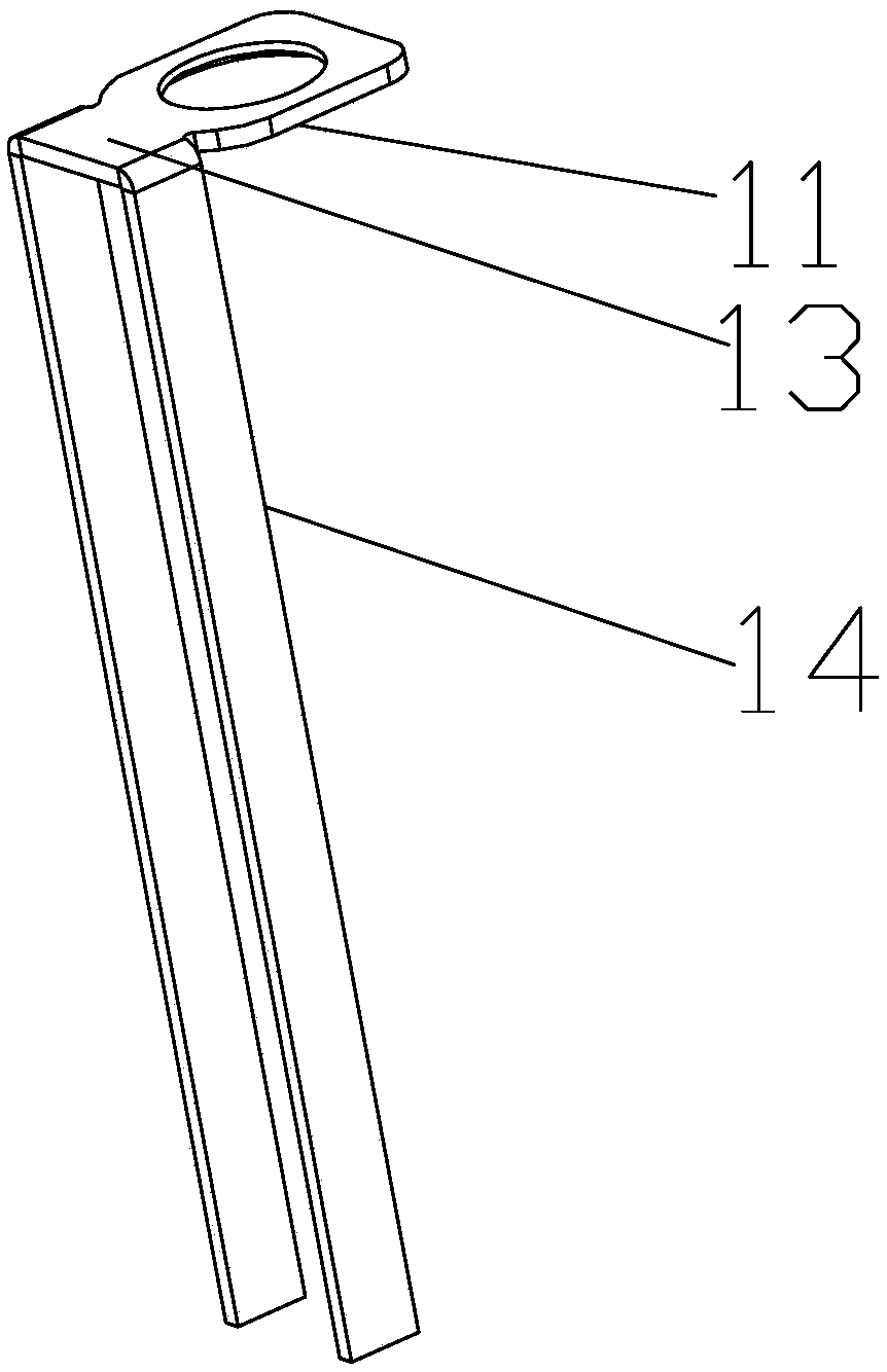
[0044] See Picture 9 The difference between this embodiment and embodiment 1 is that the connecting piece 11 and the positive pole claw 12 are integrally formed, the connecting piece two and the negative pole claw are integrally formed, and the positive pole claw structure and the negative pole claw structure are stamped separately be made of.

Embodiment 3

[0046] The difference between this embodiment and Embodiment 1 is that in this embodiment, the bending pressure of the positive pole claw is 10.2 MPa, the bending pressure of the negative pole claw is 5.2 MPa, and the bending time is 5.8 s.


PUM

PropertyMeasurementUnit
pressureaaaaaaaaaa

Abstract

The invention discloses a battery cell and cover plate assembly structure and assembly method thereof. The battery cell and cover plate assembly structure includes two bare cells and a cover plate structure, a positive electrode claw structure comprises a connecting piece and positive electrode claws, The positive electrode claw comprises a connecting piece and two positive electrode claws I arranged in parallel, a positive electrode claws I are arranged perpendicularly to a connecting piece I, a connecting part is connected to the connecting piece I, a negative electrode claw structure comprises a connecting piece II and negative electrode claws, the negative electrode claws comprises a connecting part II and two negative electrode claws I arranged in parallel, and the two bare cells arearranged side by side; The battery cell and cover plate assembly method comprises the following steps: 1) passing the positive electrode pillar through the positive electrode claw structure, lower plastic, and top cover in sequence and is connected with the positive electrode conductive block; 2) obtaining a battery cell and the cover plate preassembled structure; 3) bending the two positive electrode claws I and two negative electrode claws I respectively. The invention has the advantage that when the square battery is subjected to a squeezing test, a diaphragm is not scratched.

Description

Technical field [0001] The invention relates to the field of batteries, in particular to an assembly structure of a battery core and a cover plate and an assembly method thereof. Background technique [0002] With the widespread application of electric vehicles, prismatic batteries have also been extensively developed, and consequently the performance requirements for prismatic batteries have become higher and higher. [0003] However, the current prismatic battery is prone to scratches on the diaphragm when it is squeezed during the squeeze test or use of the prismatic battery, causing waste of resources and manpower, and also affecting the battery stability and safety of the prismatic battery. Sex. Summary of the invention [0004] Objective of the invention: In view of the above-mentioned problems, the objective of the present invention is to provide a battery cell and a cover plate assembly structure and an assembly method thereof to solve the technical problem that the diaphra...

Claims


Application Information

Patent Timeline
Patent Type & Authority Applications(China)
IPC IPC(8): H01M10/04
CPCH01M10/0404Y02P70/50
Inventor 杨伟蔡云龙陈静王俊
Owner ETRUST POWER ETP GRP LTD
Why Eureka
Try Eureka