
Bus bar module and battery pack

A bus bar module and bus bar technology, which is applied to battery pack components, batteries, and battery packs with several batteries at the same time, to achieve the effect of preventing deterioration and preventing temperature rise

Active Publication Date: 2018-12-14
YAZAKI CORP
View PDF6 Cites 8 Cited by
  • Summary
  • Abstract
  • Description
  • Claims
  • Application Information

AI Technical Summary

Problems solved by technology

Such a problem is particularly noticeable in a long bus bar module mounted to an assembled battery in which a plurality of secondary batteries (single cells) are connected in parallel

Method used


Image

  • Bus bar module and battery pack
  • Bus bar module and battery pack
  • Bus bar module and battery pack

Examples


Embodiment Construction

[0037] Hereinafter, embodiments of the present invention will be described with reference to the accompanying drawings.

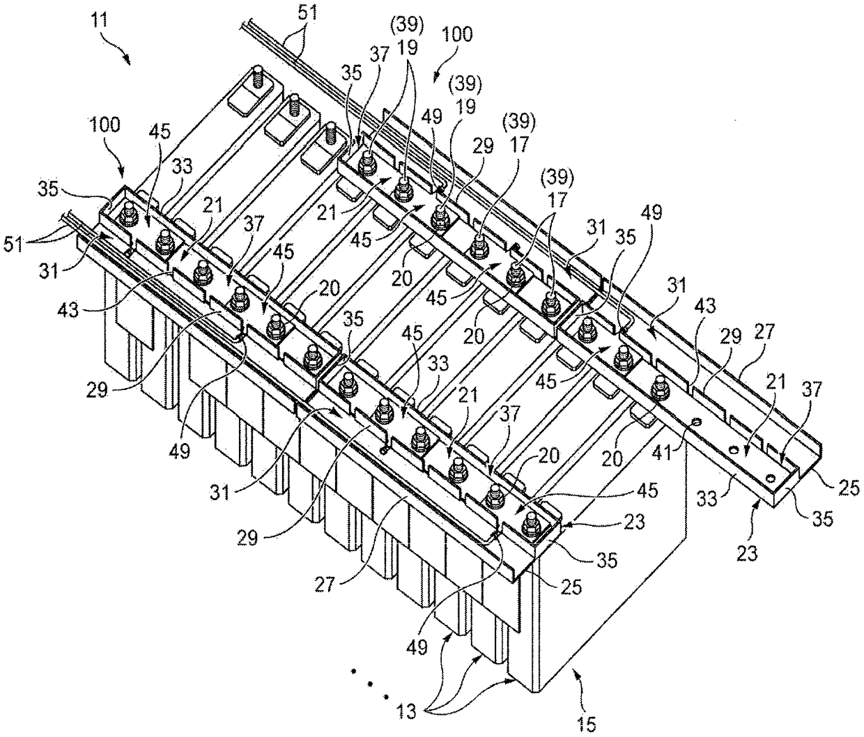
[0038] figure 1 is a perspective view illustrating a main part of the battery pack 11 to which the bus bar module 100 according to the embodiment of the present invention is mounted.

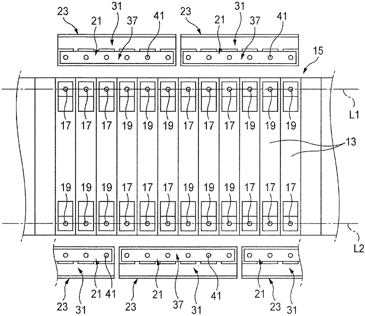
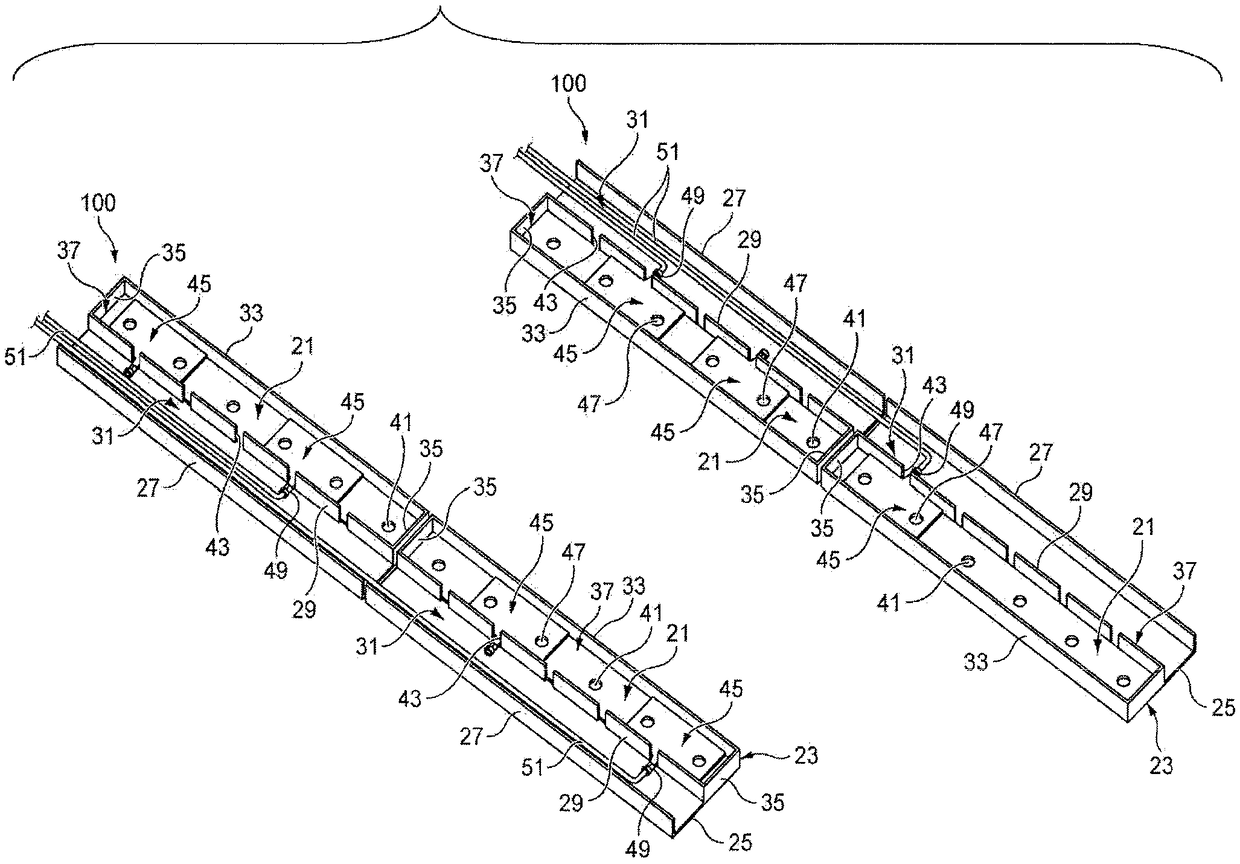
[0039] The bus bar module 100 according to this embodiment is installed in an assembled battery 15 in which a plurality of single cells 13 are arranged side by side with each other. The bus bar module 100 and the assembled battery 15 constitute the battery pack 11 .

[0040] In this embodiment, the unit cell 13 is formed in a plate shape, and is provided with a positive terminal 17 and a negative terminal 19 at both ends in the length direction in an upper end surface which is a rectangular flat surface. In this embodiment, the positive terminal 17 and the negative terminal 19 are formed in a bolt shape, but the present invention is not limited thereto. The single cells 1...


PUM


Abstract

A bus bar module includes an insulating resin case mounted to an assembled battery and including a bus bar accommodating chamber, a conductive metal bus bar, and a voltage detection terminal. The assembled battery includes a plurality of cells in which a positive terminal and a negative terminal are alternately arranged. The positive terminal and the negative terminal are collectively disposed inthe bus bar accommodating chamber. The conductive metal bus bar includes a plurality of terminal through holes corresponding to a number of the positive terminal and the negative terminal. The conductive metal bus bar is accommodated in the bus bar accommodating chamber.

Description

technical field [0001] The invention relates to a bus bar module and a battery pack. Background technique [0002] There is known a bus bar module mounted to an assembled battery provided with a plurality of plate-shaped single cells arranged close to each other in a row (arranged side by side) while facing each other's plate surfaces. ). Such as Figure 7 As shown, this type of bus bar module 501 is mounted to the battery pack so that a bus bar 505 connecting the cells is accommodated in a bus bar housing chamber portion 504 of a case 503, and a voltage detection terminal 507 for detecting the voltage of the cells passes through Electrode bolts and nuts are combined to the bus bar 505 to be fastened together with the bus bar 505 . [0003] [Patent Document 1] JP-A-2003-297334 [0004] [Patent Document 2] JP-A-2013-196907 [0005] However, if Figure 8 As shown, the bus bar 505 is manufactured by pressing a raw material plate made of conductive metal so that the bus bar...

Claims


Application Information

Patent Timeline
Patent Type & Authority Applications(China)
IPC IPC(8): H01M2/20H01M2/30H01M6/50H01M10/42H01M10/48H01M50/528H01M50/209H01M50/507H01M50/509H01M50/517H01M50/522H01M50/524H01M50/55H01M50/553H01M50/569
CPCH01M6/5011H01M6/5083H01M10/4207H01M10/4285H01M10/482H01M50/553H01M50/569H01M50/507H01M50/209H01M50/522H01M50/517H01M50/509H01M50/524H01M50/55H01M10/617Y02E60/10H01M2220/20
Inventor 柳原真一冈崎裕太郎野岛元
Owner YAZAKI CORP
Learn More