LED module glue-filling method and LED module with display surface subjected to glue filling
A technology of LED modules and display surfaces, which is applied in the direction of electrical components, circuits, semiconductor devices, etc., can solve problems such as damage and LED device drop, and achieve the effect of enhancing anti-collision
- Summary
- Abstract
- Description
- Claims
- Application Information
AI Technical Summary
Problems solved by technology
Method used
Image

Examples
Embodiment 1
[0044] This embodiment proposes a glue filling method for LED modules.
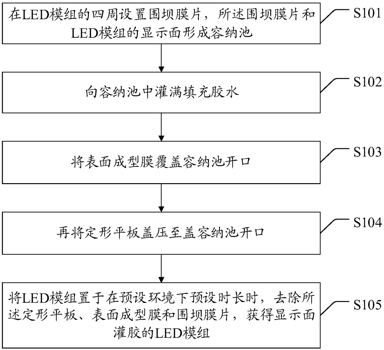
[0045] Please see figure 1 and figure 2 , the LED module glue filling method includes:
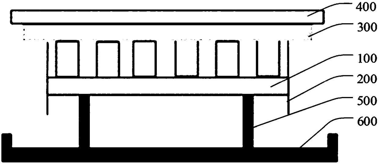
[0046] In step S101 , the dam membrane 200 is arranged around the LED module 100 , and the dam membrane 200 and the display surface of the LED module 100 form a storage pool (not marked). Among them, the dam diaphragm 200 is preferably made of hard material, and is preferably made of transparent material. And it is better to use non-stick material.
[0047] Step S102, filling the holding tank with filling glue (not marked). Among them, the filling glue has fluidity and can be filled to every position of the holding pool when it is filled. It is better to use non-foaming glue for filling glue. Filling glue can be mixed and defoamed by vacuum mixer.
[0048] Step S103 , covering the opening of the storage pool with the surface forming film 300 . Wherein, the front and back of the surface forming film 300 may ha...
Embodiment 2
[0059] This embodiment proposes a glue filling method for LED modules, and additional steps are added on the basis of the above embodiments. details as follows:
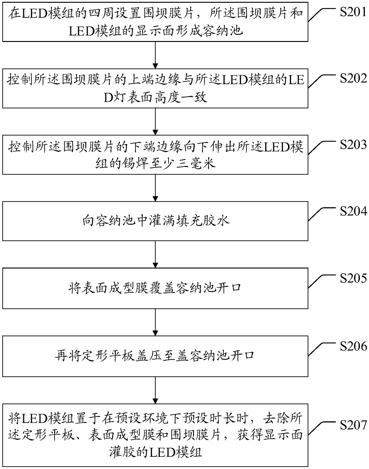
[0060] Please see image 3 , the LED module glue filling method also includes:
[0061] Step S202 , controlling the height of the upper edge of the dam diaphragm 200 to be consistent with the surface of the LED lamp of the LED module 100 .
[0062] Step S203 , controlling the lower edge of the dam diaphragm 200 to protrude downward from the soldering of the LED module 100 by at least three millimeters.
[0063] Other steps in this embodiment are the same as those in the above-mentioned embodiment, for details, please refer to the above-mentioned embodiment, and details are not repeated here.
[0064] Among them, the control scheme can be to adjust the height of the dam diaphragm in advance. When it is installed in place, the upper end of the dam diaphragm 200 has been consistent with the surface height of the LED;...
Embodiment 3
[0067] This embodiment proposes a glue filling method for LED modules, and additional steps are added on the basis of the above embodiments. details as follows:
[0068] Please see Figure 4 , the LED module glue filling method also includes:
[0069] Step S304, placing the LED module 100 on the bracket 500, so that the back of the LED module 100 is suspended and the display surface is horizontal.
[0070] Wherein, the bracket 500 may be a single thick column bracket, or multiple thin column brackets.
[0071] Other steps in this embodiment are the same as those in the above-mentioned embodiment, for details, please refer to the above-mentioned embodiment, and details are not repeated here.
[0072] In the LED module glue filling method provided in this embodiment, the back of the LED module 100 is suspended in the air through a bracket, so that the back of the LED module 100 can be prevented from being stained with filling glue. When the LED module 100 is supported horizo...
PUM
 Abstract
Description
Claims
Application Information
 - Generate Ideas
- Intellectual Property
- Life Sciences
- Materials
- Tech Scout
- Unparalleled Data Quality
- Higher Quality Content
- 60% Fewer Hallucinations
Browse by: Latest US Patents, China's latest patents, Technical Efficacy Thesaurus, Application Domain, Technology Topic, Popular Technical Reports.
© 2025 PatSnap. All rights reserved.Legal|Privacy policy|Modern Slavery Act Transparency Statement|Sitemap|About US| Contact US: help@patsnap.com