An electromagnetic clutch coil automatic cloth winding device

An electromagnetic clutch and automatic technology, applied in coil manufacturing, inductance/transformer/magnet manufacturing, circuits, etc., can solve the problems of cutting short insulation cloth and low degree of automation, so as to achieve convenient take-out work, reduce labor output, and high-efficiency leak prevention effect of effect

Inactive Publication Date: 2018-12-14
阜阳运筹生产力促进中心有限公司
View PDF1 Cites 2 Cited by
  • Summary
  • Abstract
  • Description
  • Claims
  • Application Information

AI Technical Summary

Problems solved by technology

[0005] The purpose of the present invention is to address the deficiencies of the prior art, on the basis of automatically winding the forming assembly by setting the upper cloth assembly, and then using the cloth cutting mechanism, under the support of the support plate, the interlocking unit drives the cut piece The unit cuts the wrapped cloth in time, so as to solve the technical problem that the insulating cloth needs to be cut manually and glued to seal in the winding process, and the degree of automation is not high. High, high production capacity, saving labor output

Method used


Image

  • An electromagnetic clutch coil automatic cloth winding device
  • An electromagnetic clutch coil automatic cloth winding device
  • An electromagnetic clutch coil automatic cloth winding device

Examples


Embodiment 1

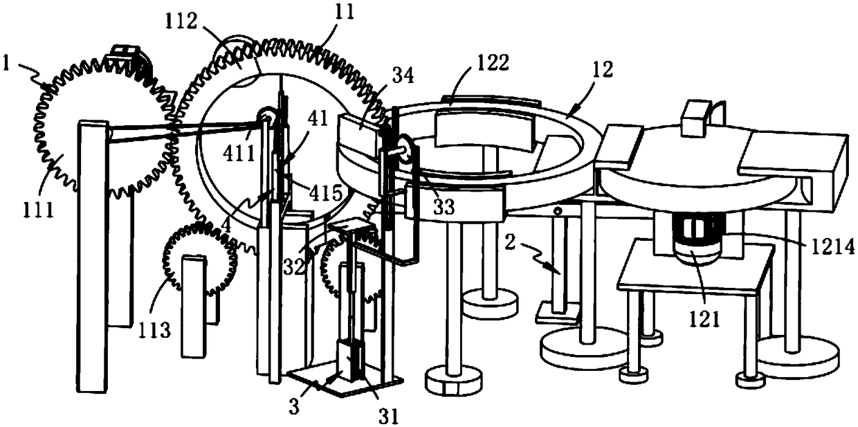
[0081] Such as figure 1 As shown, an electromagnetic clutch coil automatic winding device, including:

[0082] Cloth winding mechanism 1, said cloth winding mechanism 1 comprises a vertically placed upper cloth assembly 11 and a forming assembly 12 arranged behind said upper cloth assembly 11 and perpendicular to said upper cloth assembly 11;

[0083] A glue-fixing mechanism 2, the glue-fixing mechanism 2 is arranged on one side of the molding assembly 12 and is located at the lower end of the molding assembly 12;

[0084] Cloth cutting mechanism 3, the cloth cutting mechanism 3 is arranged on the other side of the forming assembly 12 relative to the glue fixing mechanism 2; and

[0085] The release mechanism 4, the release mechanism 4 is arranged on the upper cloth assembly 11, which includes a control assembly 41 that moves up and down along the height direction of the upper cloth assembly 11 and is arranged in cooperation with the control assembly 41 and installed on the u...

Embodiment 2

[0147] Such as Figure 7 , Figure 8 As shown, the components that are the same as or corresponding to those in the first embodiment are marked with the corresponding reference numerals in the first embodiment. For the sake of simplicity, only the differences from the first embodiment will be described below. The difference between this embodiment two and embodiment one is:

[0148] further, such as Figure 7 , Figure 8 Shown, described glue solid mechanism 2 comprises:

[0149] A control unit a21, the control unit a21 includes a protruding rod 211 fixedly arranged on the upper surface of the edge of the turntable 1213 and an upper pressure block 212 fixedly arranged at the end of the protruding rod 211 and located below;

[0150] The base rod 22, the base rod 22 is located between the turntable 1213 and the induction coil 1224 and is arranged vertically upward;

[0151]The control unit b23, the control unit b23 includes a tilting rod 231 hinged to the base rod 22, a low...


PUM


Abstract

The invention relates to an electromagnetic clutch coil automatic cloth winding device, comprising a cloth winding mechanism which comprises an upper cloth assembly vertically arranged and a molding assembly arranged behind the upper cloth assembly and perpendicular to the upper cloth assembly; A gluing mechanism disposed on one side of the molding assembly and located at a lower end of the molding assembly; A cloth cutting mechanism disposed on the other side of the molding assembly with respect to the gluing mechanism; And a release mechanism arranged on the upper cloth assembly and comprising a control assembly moving up and down along the height direction of the upper cloth assembly and a flick assembly arranged in cooperation with the control assembly and mounted on the upper cloth assembly; The invention solves the technical problem that the insulation cloth needs to be cut manually and glued to be sealed in the winding process, and the degree of automation is not high.

Description

technical field [0001] The invention relates to the technical field of inductance coils, in particular to an automatic cloth winding device for electromagnetic clutch coils. Background technique [0002] The inductance coil is a device that uses the principle of electromagnetic induction to work. When a current flows through a wire, a certain electromagnetic field will be generated around the wire, and the wire itself of this electromagnetic field will be in the range of this electromagnetic field. The wire in the coil is induced, and it needs to be put into the shell before it is put into use. When pouring epoxy resin, in order to prevent the epoxy resin from penetrating into the coil, a layer of cloth needs to be wound on the inductor coil. [0003] Patent No. CN108428548A discloses a motor rectangular coil automatic winding insulation cloth robot, including continuous winding module, trajectory profiling module and card loading module, the invention has the advantages of ...

Claims


Application Information

Patent Timeline
IPC IPC(8): H01F41/12
CPCH01F41/12H01F41/125
Inventor 杨绪明
Owner 阜阳运筹生产力促进中心有限公司
Why Eureka
Try Eureka