
Small high-definition ultra-short throwing projection lens

A technology of projection lens and ultra-short focus, which is applied in optics, instruments, projection devices, etc., can solve problems such as difficulty in adapting to the needs of small projection equipment, lower picture definition, and unsatisfactory screen effects, etc., to achieve excellent image quality and small distortion , the effect of precise structure

Pending Publication Date: 2018-12-14
杭州有人光电技术有限公司
View PDF0 Cites 7 Cited by
  • Summary
  • Abstract
  • Description
  • Claims
  • Application Information

AI Technical Summary

Problems solved by technology

The design of ultra-short-throw projection lens generally uses an aspheric mirror to project the projection image directly onto the screen, but the processing of large-diameter aspheric mirrors is difficult, and it is difficult to industrialize
And the effect of using a spherical reflector to project directly onto the screen is not ideal
At the same time, the F number of the projection lens of the existing projector is relatively high, and if the F number is reduced, the clarity of the picture will be reduced.
[0003] In addition, the existing ultra-short-focus lens design contains multiple lens numbers and has a large lens volume, which is difficult to meet the needs of existing small projection equipment

Method used


Image

  • Small high-definition ultra-short throwing projection lens
  • Small high-definition ultra-short throwing projection lens
  • Small high-definition ultra-short throwing projection lens

Examples


Embodiment 1

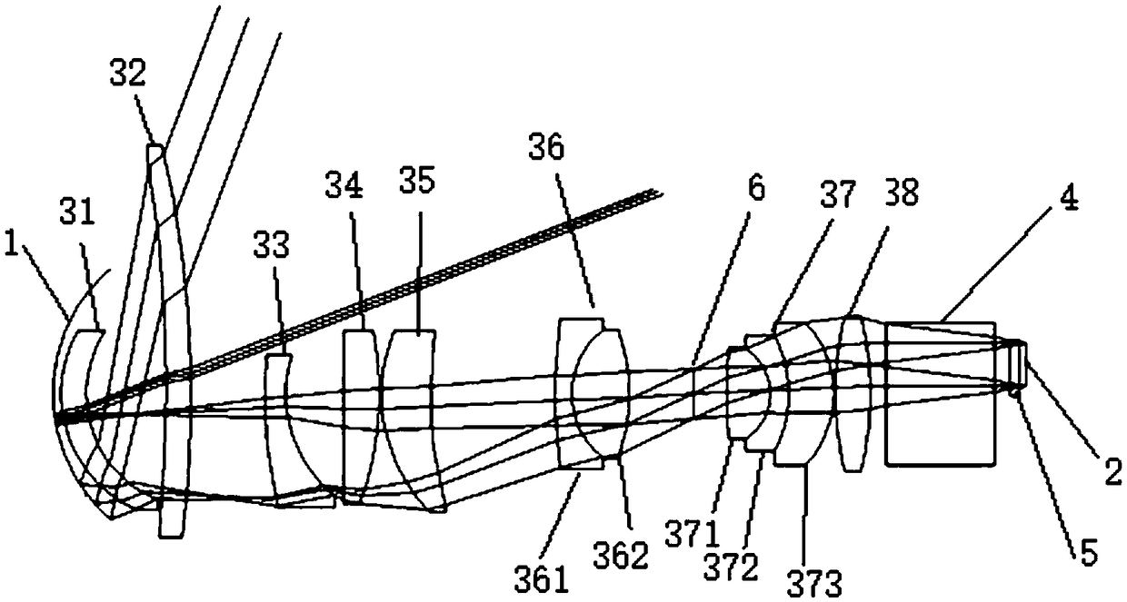
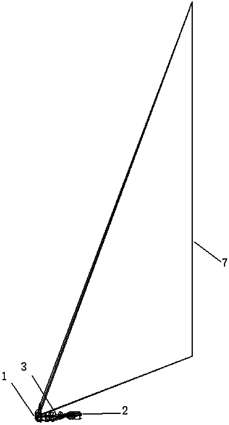
[0025] Embodiment 1: as figure 1 As shown, the present invention provides a small ultra-short-focus high-definition projection lens, including a reflector 1, a lens assembly 3, a prism group 4, a window glass 5, a diaphragm 6 and a projection lens arranged between the DMD chip 2 and the projection surface 7. Surface 7.

[0026] The reflector is a spherical reflector and includes a concave surface facing the first positive meniscus lens 31.

[0027] The DMD chip is 0.3 inches, and the resolution is 1280×720 and 0.33 inches 1368×768; the DMD chip is perpendicular to the optical axis of the lens assembly, the center of the chip is deviated from the center of the lens, the long side of the chip is perpendicular to the off axis and the center of the lens is at outside the chip area.

[0028] The several coaxial arrangements of the lens assembly from the mirror to the DMD chip include a first positive meniscus lens 31, a second positive meniscus lens 32, a first concave lens 33, a...


PUM


Abstract

The invention discloses a small high-definition ultra-short throwing projection lens. The focal length is between 2mm-2.5mm, the lens comprises a plurality of coaxially arranged optical lens between aprojection plane and a DMD chip and a reflector; the plurality of coaxial arrangement orders of the optical lens modules between the reflector and the DMD chip comprise a first positive meniscus optical lens, a second positive meniscus optical lens, a first concave optical lens, a first convex optical lens, a second convex optical lens, a doublet, a triplet and a third convex optical lens; a projection beam modulated by the DMD chip orderly passes through the optical lens modules and the reflector and is imaged on the projection plane. By using the special optical lens structure and the spherical reflector, the first two optical lenses experience positive and negative transmission for twice, the amount of the optics required by the lens is reduced, the lens volume is greatly reduced, andthe projection lens can be applied to the small projection equipment and can achieve the relatively high definition and TV distortion requirement of the aspheric surface.

Description

technical field [0001] The invention belongs to the field of photoelectric projection technology, in particular to a small high-definition ultra-short-focus projection lens. Background technique [0002] At present, projectors with higher pixels generally use aspherical projection lenses, and the requirements for definition and TV distortion are relatively easy to meet. The design of ultra-short-throw projection lens generally uses an aspheric mirror to directly project the projection image onto the screen, but the processing of large-diameter aspheric mirrors is difficult and difficult for industrialization. The effect of using a spherical reflector to directly project onto the screen is not ideal. At the same time, the F-number of the projection lens of the existing projector is relatively high, and if the F-number is reduced, the definition of the picture will be reduced at the same time. [0003] In addition, the existing ultra-short-focus lens design includes multiple...

Claims


Application Information

Patent Timeline
Patent Type & Authority Applications(China)
IPC IPC(8): G02B13/02G02B13/00G02B13/18G03B21/14
CPCG02B13/0045G02B13/02G02B13/18G03B21/142
Inventor 周伟统
Owner 杭州有人光电技术有限公司
Learn More