A method for calculating the inflating volume of an internal combustion engine

A technology of internal combustion engine and air charge, which is applied in the field of computer programs, can solve inaccurate problems and achieve the effect of reducing emissions

Active Publication Date: 2018-12-14
ROBERT BOSCH GMBH
View PDF13 Cites 0 Cited by
  • Summary
  • Abstract
  • Description
  • Claims
  • Application Information

AI Technical Summary

Problems solved by technology

As a result, depending on the dynamics of the actuators, for example based on driving desires, the determination is partly particularly inaccurate

Method used


Image

  • A method for calculating the inflating volume of an internal combustion engine
  • A method for calculating the inflating volume of an internal combustion engine
  • A method for calculating the inflating volume of an internal combustion engine

Examples


Embodiment Construction

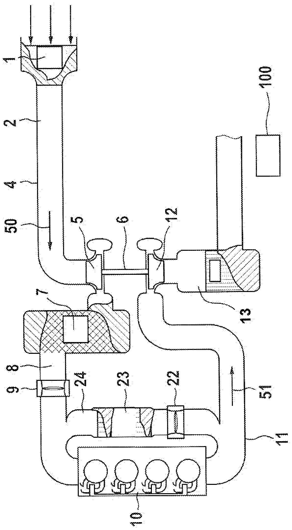
[0029] figure 1 The schematic representation shows an internal combustion engine 10 with an air system 4 via which the internal combustion engine 10 is supplied with air 50 , and an exhaust system 11 via which the exhaust gas 51 flows from all exhausted from the internal combustion engine 10 described above). In the air system 4 , viewed in the flow direction of the air 50 , there are arranged: an air filter 1 , a hot film air mass sensor (HFM) 2 , a compressor 5 of an exhaust gas turbocharger 6 , a charge air Cooler 7 and throttle valve 9. Instead of or in addition to HFM sensor 2 , a pressure-based air flow meter (PFM) sensor 8 for determining the air mass flow can also be used. The positioning of the hot film air quality sensor 2 can be changed within the air system 4 . Furthermore, internal combustion engine 10 has a camshaft adjustment device, which is not further shown in the drawing. The opening and closing times of the valves can be determined and varied for the co...


PUM


Abstract

The invention relates to a method for calculating the inflating volume of an internal combustion engine (10). The inflating volume is determined by utilizing at least one first calculation network anda second calculation network. Switching between at least one first measuring network and a second measuring network is performed according to at least one operation parameter and / or operation state of the internal combustion engine (10).

Description

technical field [0001] The invention relates to a method for calculating the air charge of an internal combustion engine according to the independent claims. Furthermore, the invention relates to a computer program which is configured to carry out one of the methods. Background technique [0002] In internal combustion engines, in order to calculate the air charge in the cylinder, the model calculates physical variables such as mass flow through the throttle valve, mass flow through the intake valve, air mass and residual gas mass in the combustion chamber / cylinder. As a rule, these calculations are carried out in an ignition-synchronous or angle-synchronous measurement grid, wherein, for example, the ignition of a cylinder of an internal combustion engine is used as an event for the measurement grid. The measured variables determined by means of the measuring grid are, inter alia, the pressure in the intake tract, the rotational speed and the positions of the intake and ex...

Claims


Application Information

Patent Timeline
IPC IPC(8): F02D41/00F02D41/24
CPCF02D41/0002F02D41/2432F02D2200/101F02D41/187F02D2041/1433F02D2200/0402F02D2200/0406F02D2200/0408F02D2250/12F02D2250/14
Inventor A.艾弗M.海恩科勒M.杜荣P.K.H.杜伽帕R.麦尔
Owner ROBERT BOSCH GMBH
Why Eureka
Try Eureka