Foundation reinforcement device and use method thereof

A technology of foundation reinforcement and foundation device, applied in the field of infrastructure construction, can solve the problems of lower reinforcement strength, lower strength of foundation flange, inability to disassemble, etc., and achieves the effect of reliable reinforcement, avoiding uneven foundation flange, and convenient disassembly and adjustment.

Pending Publication Date: 2018-12-14
JIANGSU GUOHUA TUBE TOWER MFR
View PDF0 Cites 0 Cited by
  • Summary
  • Abstract
  • Description
  • Claims
  • Application Information

AI Technical Summary

Problems solved by technology

[0003] In the process of tower construction, the foundation needs to be fixed to prevent adverse problems caused by the instability of the foundation of the tower due to the natural environment. The traditional method of pre-embedding with anchor bolts can only play a good role in fixing at the beginning , but due to the different installation environments, the anchor bolts are exposed to the air for a long time, which is easy to cause different degrees of corrosion, resulting in a reduction in its reinforcement strength. For example, when the original M50 anchor bolts are corroded, their strength may drop by 30%. As a result, the reinforcement requirements cannot be met, and the threads are easily corroded, making it impossible to disassemble. In addition, the pipe tower itself is relatively tall, and the method of disassembling and replacing one by one not only makes it difficult to handle, but also the anchor bolts are severely corroded, making disassembly more difficult. , and the method of continuing to punch holes on the foundation flange will easily cause the strength of the foundation flange to decrease

Method used


Image

  • Foundation reinforcement device and use method thereof
  • Foundation reinforcement device and use method thereof
  • Foundation reinforcement device and use method thereof

Examples


Embodiment Construction

[0024] The present invention will be further described below in conjunction with accompanying drawing.

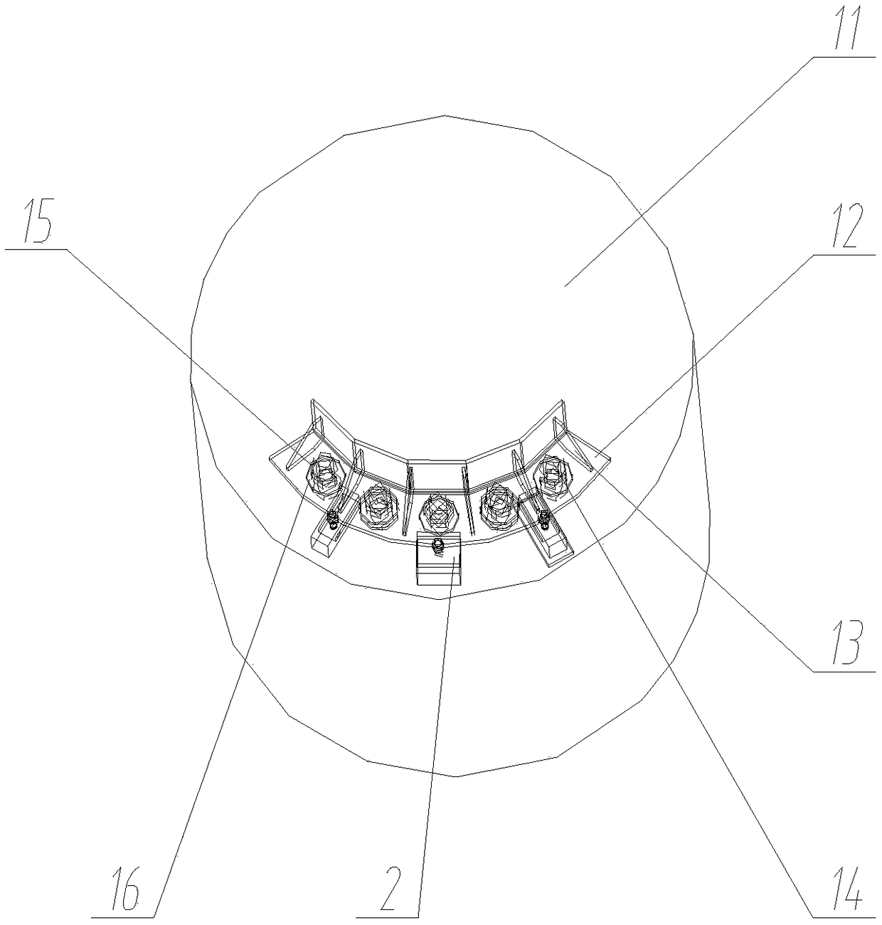
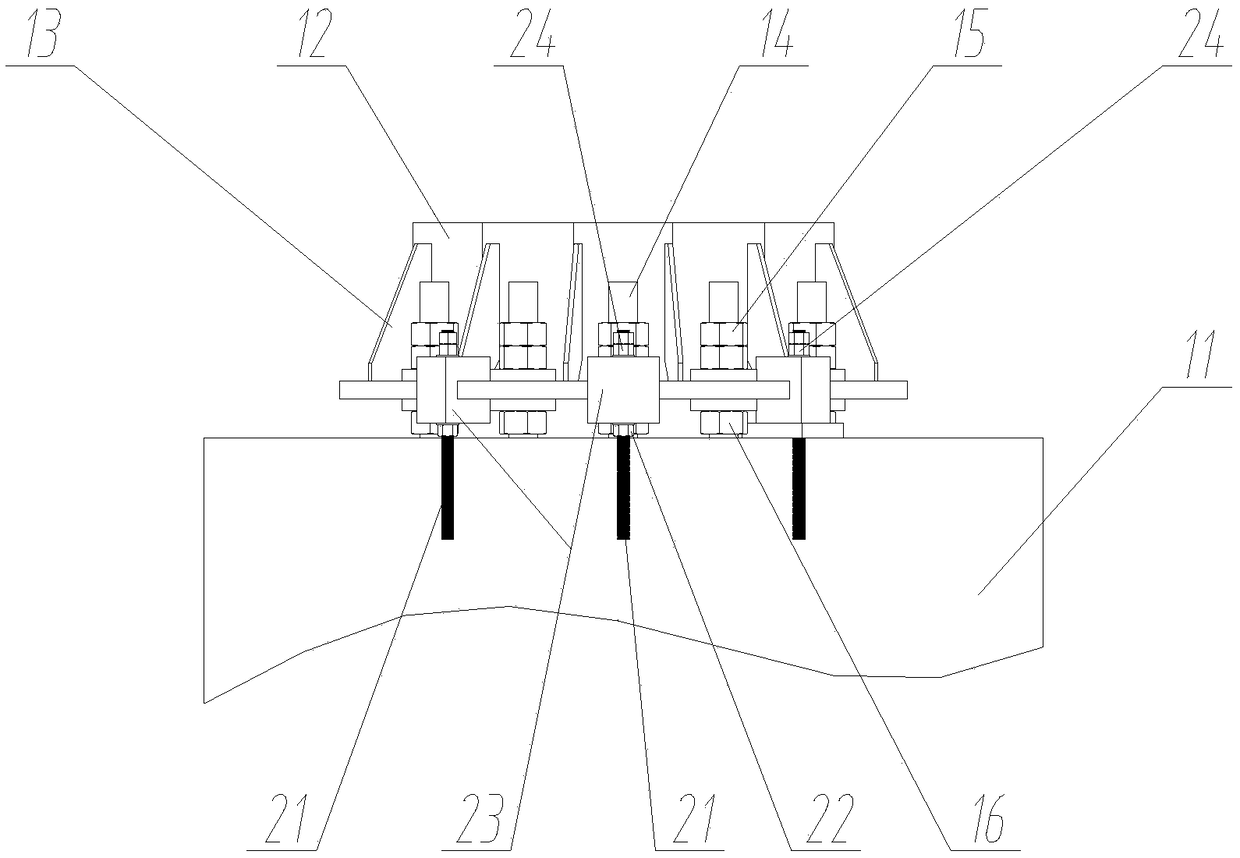
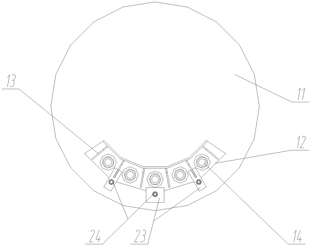
[0025] Such as Figure 1 to Figure 4 As shown, the foundation reinforcement device and its method of use include foundation device and reinforcement device 2;

[0026] The foundation device includes a foundation seat 11, a foundation flange 12 and anchor bolts 14; the number of anchor bolts 14 is evenly distributed on the foundation seat 11, and the lower part of the anchor bolts 14 is embedded in the In terms of basic settings, round holes are set on the base flange 12, and are set on the anchor bolts 14 through the round holes. Strengthening plates 13 are set on the base flange 12. There are several reinforcing plates 13, and the circumference Evenly distributed on the base flange 12, the upper lock nut 15 and the lower lock nut 16 are threaded on the anchor bolt 14, the upper lock nut 15 is located on the upper side of the base flange 12, and the lower lock nut The nut...


PUM


Abstract

The invention discloses a foundation reinforcing device and a use method thereof. The foundation reinforcing device comprises a foundation device and a reinforcing device body, an upper locking nut and a lower locking nut are arranged on a foundation bolt in a thread manner, the upper locking nut is located on the upper side of a foundation flange, the lower locking nut is located on the lower side of the foundation flange, the reinforcing device body comprises a reinforcing plate and a reinforcing bolt, the reinforcing plate is provided with a penetrating groove with a leftward opening and athrough hole in the up and down direction, the penetrating groove of the reinforcing plate wraps the upper end and the lower end of the edge of the foundation flange, the reinforcing bolt penetrates the bolt and is located on the outer side of the foundation flange, an upper reinforcing nut and a lower reinforcing nut are in threaded connection to the reinforcing bolt, the lower portion is embedded in a foundation base, the upper reinforcing nut is located on the upper side of the reinforcing plate, and the lower reinforcing nut is located on the lower side of the reinforcing plate. Accordingto the foundation reinforcing device and the use method thereof, the structure is simple, the foundation bolt foundation can be rapidly reinforced, the condition that in the use process, strength is reduced is avoided, and the device is suitable for infrastructure construction of rod towers and the like of industries like power and communication.

Description

technical field [0001] The invention relates to the field of infrastructure construction such as poles and towers in industries such as electric power and communication, and specifically relates to a foundation reinforcement device and a method for using the same, which are suitable for foundation reinforcement of communication towers, power poles, and the like. Background technique [0002] With the development of electric power and communication technology, my country has realized the transmission of short-distance circuits and communications, but for the long-distance transmission of electric power and communications and maintaining stability, towers are still essential as a transition for transfer and transmission. [0003] In the process of tower construction, the foundation needs to be fixed to prevent adverse problems caused by the instability of the foundation of the tower due to the natural environment. The traditional method of pre-embedding with anchor bolts can on...

Claims


Application Information

Patent Timeline
Patent Type & Authority Applications(China)
IPC IPC(8): E02D27/42
CPCE02D27/42
Inventor 谢为昌沈小杰吉光辉
Owner JIANGSU GUOHUA TUBE TOWER MFR
Why Eureka
Try Eureka